A wiring diagram is a simplified traditional photographic depiction of an electrical circuit. Example 63nhefa63753ll would be the spec for other onan rv generator parts not listed on our website please contact your local onan distributor.
Onan Stuff
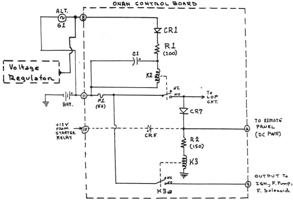
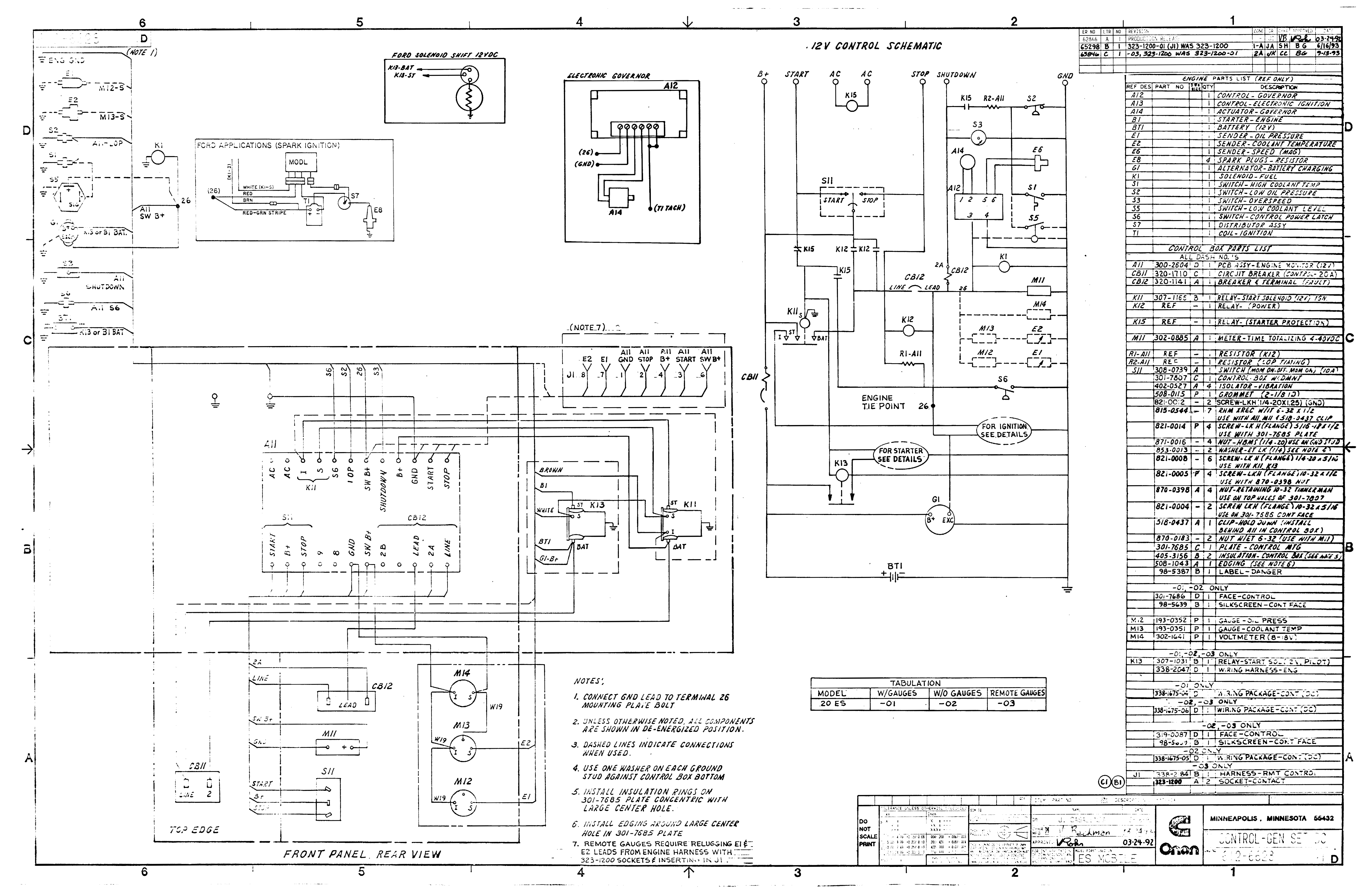
Onan emerald 3 wiring diagram. Dimensions 2 l x 4 w. Variety of onan rv generator wiring diagram. Rv wiring onan onan generator wiring 4kw onan emerald 3 wiring onan diagram onan rv generator wiring diagram wiring diagram for onan. Onan 300c859 conversion diagram. Eliminate the 4 wire connector by hard wire bypass. It reveals the elements of the circuit as simplified forms and also the power and also signal connections between the gadgets.
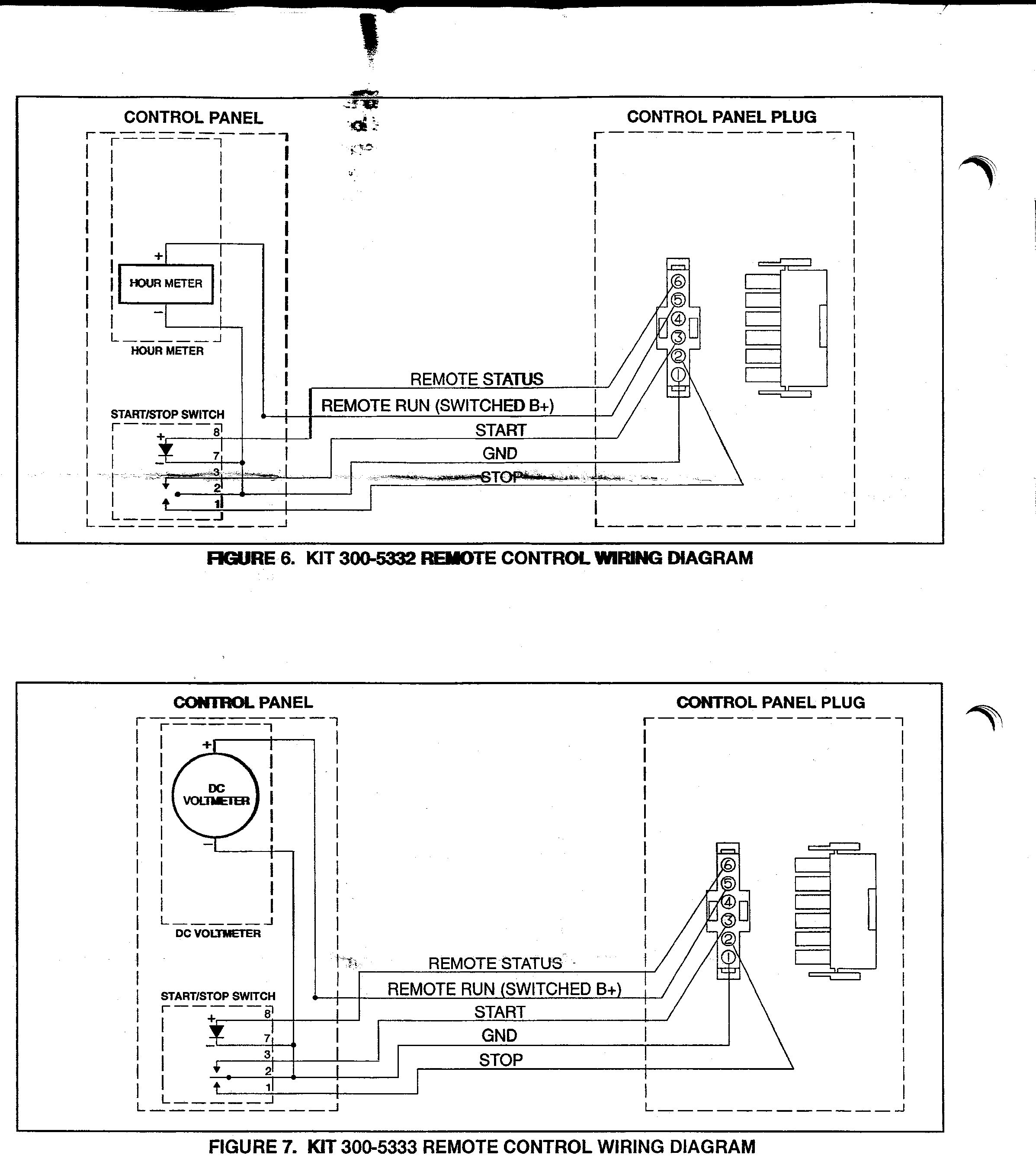
Typical wiring diagram cap. Suspect the 4 wire connector faulty located in onan compartment floor. 1 genset wiring diagram onan bge emerald 1 onan emerald 1 genset onan emerald 1 genset wiring diagram onan generator bge emerald 1 genset wire diagram to onan genset 3 generator wiring diagram march 5 2020 april 12 2020 wiring diagram by anna r. Press remote control panel start and stop switch onan should respond. A wiring diagram is a streamlined traditional pictorial representation of an electrical circuit. Wiring conn wiring cat remote control 110 feet feet l and nh spec l control assy 30 amp amp amp remote control 12v onan not used spark pump or fuse fuge s amp v start solenoid crank ignition figure 40.
This is a typical ignition coil for an onan engine. Verify the condenser is not grounded. Onan gen 10 model 10hdcaaa onan gen 10 model 10hdcaaa sn bit will run for about 15 sec then. The spec letter of your generator is the last letter in the full model. No continuity means a bad wire. Replace both of them.
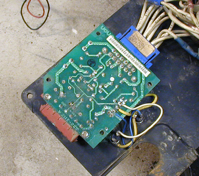
My question does this wiring diagram eliminate the c board and. Onan generator replacement board c boards for onan generators are made in the usa. Onan generators restoring operating and maintaining vintage. Below are two charts of common repair parts for onan nhe nhel emerald iii series. Assortment of onan emerald 1 genset wiring diagram. Remove wires from upper board terminals 1 2 and 3.
This is a typical ignition module for an onan engine. It shows the components of the circuit as streamlined forms and also the power as well as signal links between the tools. The first chart is for spec range a c and the second chart is for spec range d p. Model c replaces onan c color green. Jumper upper terminal 1 to 3 onan should start. Remove the condenser and check for continuity between the end of the wire and the mounting bracket of the condenser.
You should read no continuity.
Gallery of Onan Emerald 3 Wiring Diagram