The fcm 1 rel module must be programmed with the correct releasing type code listed in the nfs 320ec programming manual. Variety of notifier fcm 1 wiring diagram.
Notifier Nfs2 3030 Manuals
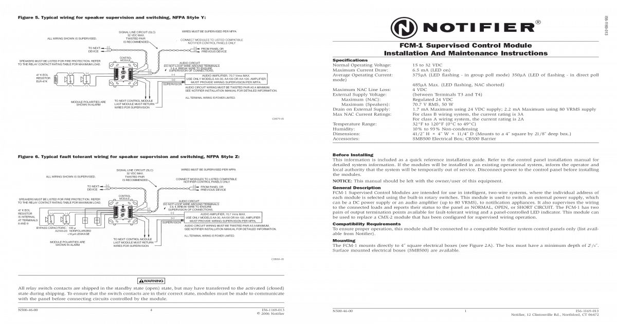
Notifier fcm 1 rel wiring diagram. 65 ma led on temperature range. If no confirmation is received the module will automatically reset. It will then enter a 3 second window awaiting a pair of confirmation signals. 32f to 120f 0c to 49c dimensions. Fcm 1a installation document i56 1169. 15 to 32 vdc.
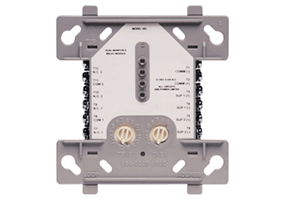
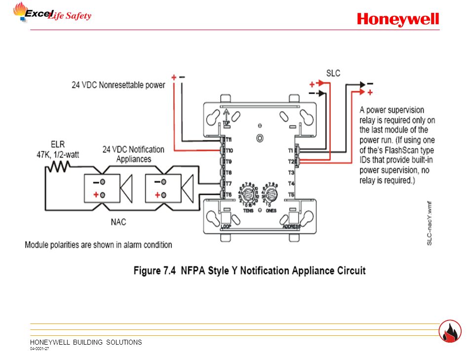
Fmm 1 connect modules to listed compatible notifier control panels only. All wiring must conform to applicable local codes ordi. 5 for frm 1 general fcm 1 control module the fcm 1 addressable control module provides notifier intelligent control pan els a circuit for notification appliances horns strobes speak ers etc or to monitor a telephone circuit. Dn 6724 040504 page 1 of 4 fcm 1 module see wiring diagram fig. Connecting a releasing device to the fcm 1 rel. Compatible notifier system control panel list available from noti fier.
All wiring shown is supervised and power limited. Maximum slc current draw. Compatible notifier system control panels only list available from notifier. The box must have a minimum depth of 218. Current rating maximum voltage load description application. Mounting the fcm 1 mounts directly to 4 square electrical boxes see figure 2a.
Releasing applications c limited energy cable cannot be used to wire a. Notifier nfse manual online. Install contact closure devices per manufacturers installation instructions. If using the on board nacs see circuit requirements for section 474 connecting a releasing device to the control panel on page 44. 16112018 16112018 3 comments on notifier fcm 1 wiring diagram. For installation instructions see the following documents.
Ing power limited and non power limited wiring in the same junction box as fcm 1a. Notifier fcm 1 wiring diagram. Connecting a releasing device to a fcm 1 module connecting an. Frm 1a installation document i56 3502. Maximum slc current draw. Surface mounted electrical boxes smb500 are available from notifier.
Notifier nfs manual online. The fcm 1 rel releasing control module uses a redundant protocol. Any number of ul listed contact closure devices may be used. All wiring must conform to applicable local codes ordi. Page 5 wiring diagrams this page. The module must be armed with a pair of signals in order to activate.
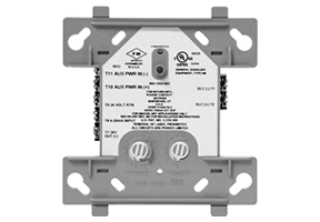
15 to 32 vdc. 4675 h x 4275 w x 14 d mounts to a 4 square by 218 deep box specifications for frm 1. It reveals the parts of the circuit as streamlined forms and the power as well as signal links in between the tools. Surface mounted electrical boxes smb500 are available. Notifier slc wiring manual document 51253. Mounting the frm 1 mounts directly to 4 square electrical boxes see fig ure 2a.
The box must have a minimum depth of 21 8. A wiring diagram is a simplified conventional pictorial representation of an electric circuit.
Gallery of Notifier Fcm 1 Rel Wiring Diagram