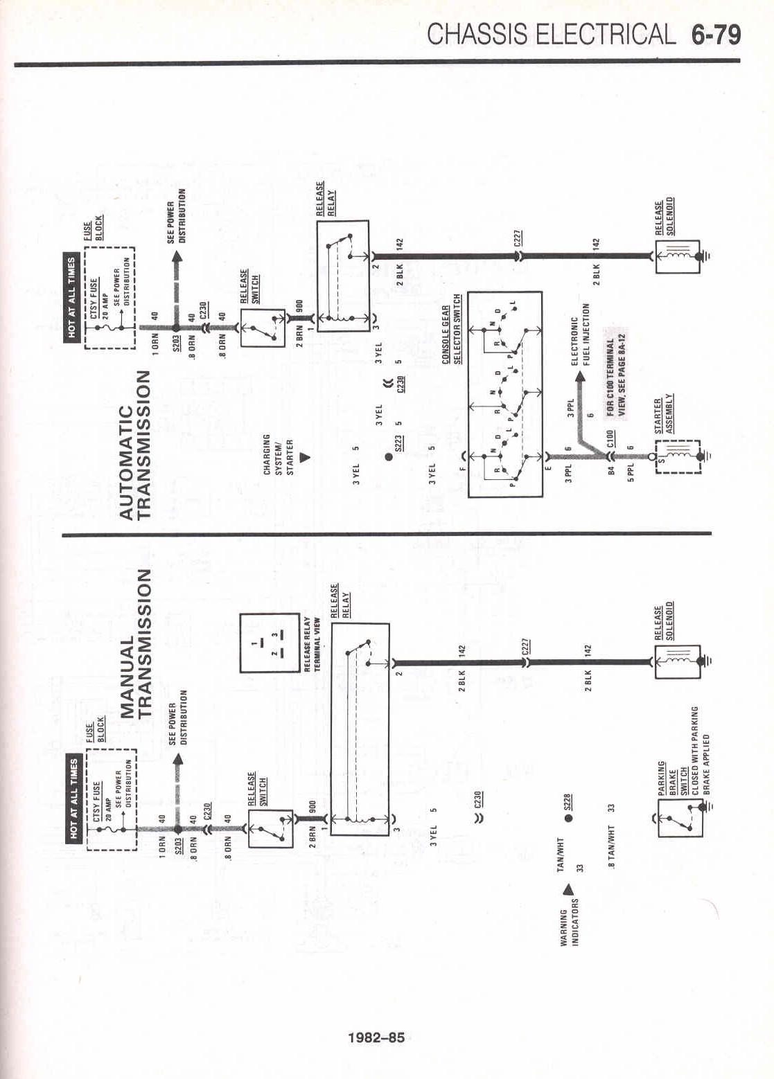
Volvo penta starter wiring diagrahm volvo penta starter wiring diagrahm is one of the best book in our library for free trial. It shows the components of the circuit as simplified shapes and the capacity and signal associates together with the devices.

Cbm Motorsports Mefi 4 Electronic Control Modual Technical
Volvo penta ecu wiring diagram. Volvo penta wiring diagram wiring diagram is a simplified all right pictorial representation of an electrical circuit. There are also many ebooks of related with volvo penta starter wiring diagrahm. Hello im working on my 2002 glastron sx175 powered by a volvo penta 30l gsm c est delco ignition and its carbureted. Mefi 3 4 engine electronic control system. We provide copy of volvo penta starter wiring diagrahm in digital format so the resources that you find are reliable. I took ownership over about 2 years ago.
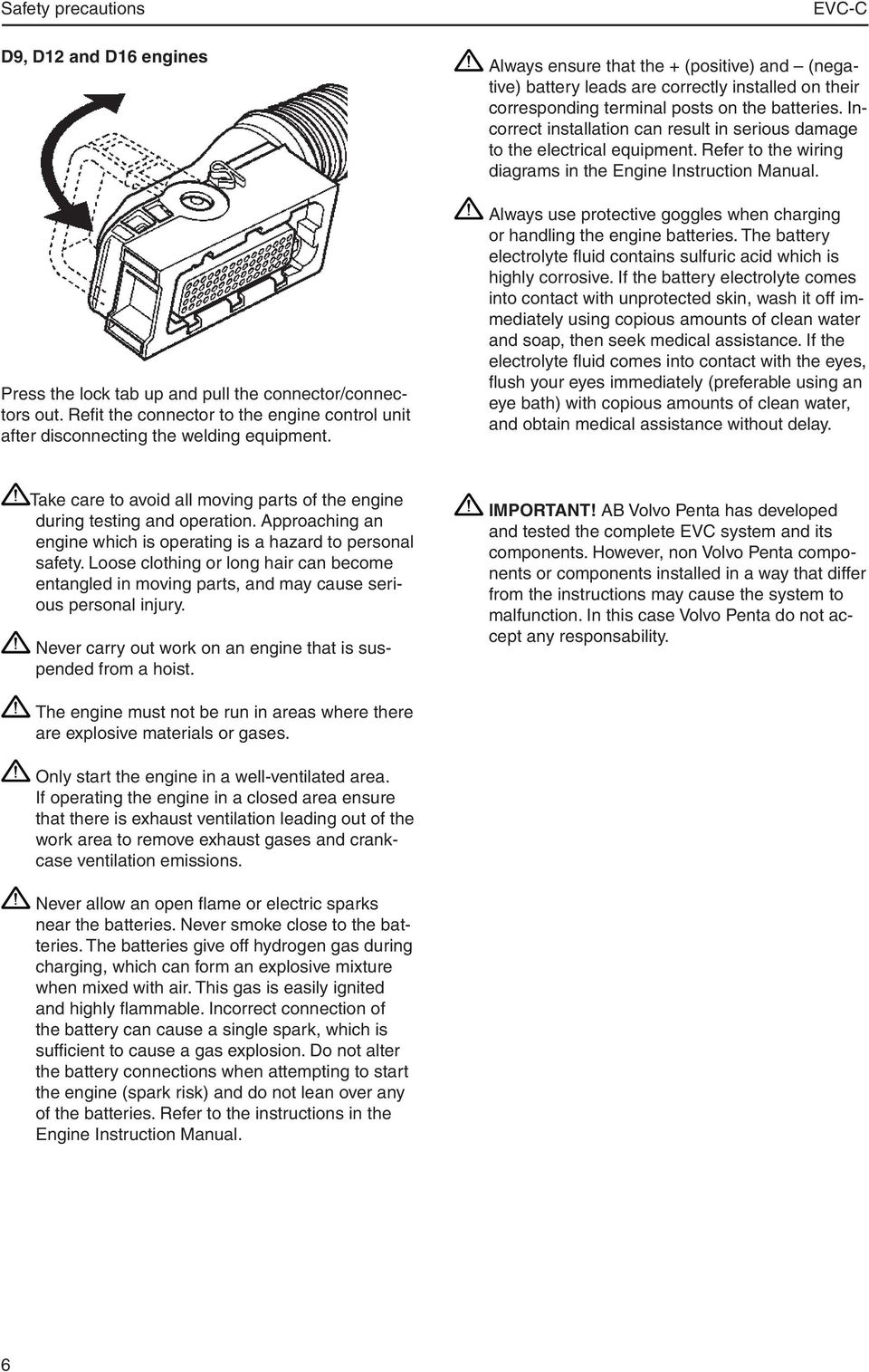
Ab volvo penta has developed and tested the entire evc system and its components. Refer to the wiring diagram in the engine operators manual. Wrong connection may cause severe damage to electrical equipment. 2007 volvo s60 s60r wiring diagram tp 3997202rar 2007 volvo v70 v70r xc70 xc90 wiring diagram tp 3998202rar 2013 volvo s60 11 electrical wiring diagram tp 39255202rar. Ag vehicle ecu 14 ems power control 9 ah vehicle ecu 24 10 ai vehicle ecu 34 11. Volvo penta 57 gi engine.
Volvo engine 29 cc engine control isx export 30 cd engine control export 31. Volvo penta engine workshop manual toyota corolla electrical wiring diagrams 2009 2010 toyota celica 2004 electrical wiring diagrams ferrari 328 gtb 328 gts wiring diagram 1989 1999 toyota corolla. Mefi 1 2 engine electronic control system. This winter my plan was to rewire all the splices that had been done over the years. Volvo prosis 2019 parts service diagnostic version 316280 spare parts catalog workshop manuals repair manuals diagrams manuals wiring diagrams hydraulic diagrams etc for all volvo construction equipment. However components supplied from manufacturers other than volvo penta or components incorrectly installed may cause the system.
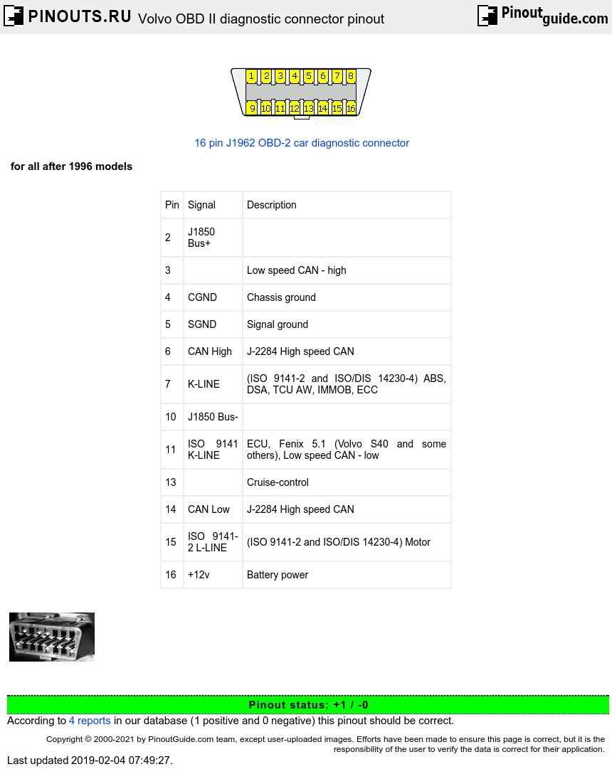
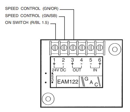
Wiring diagram index name description page aa power distribution frc 3. Wiring color and pin out schematic electronic vessel control evc ec c volvo penta ips 1 blgn 2 sbgn 3 blbn 4 sbbn 5 grbl 6 sbbl 12 sbgr 11 sb 10 gror 9 blor 8 r 7 evc control panel x4 x3x7 x2 x5 multilink multilink breakout y split 1 ygr 2 ygr 3 yw r 6 yw 5. Ecm egc engine control module. Diagnosis function with help available.
Gallery of Volvo Penta Ecu Wiring Diagram