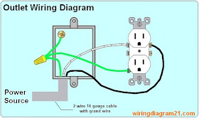
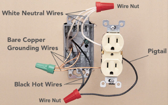
This diagram shows the wiring for multiple switched outlets on one switch. At the outlets each is wired using a pigtail splice to make the hot and neutral connections.
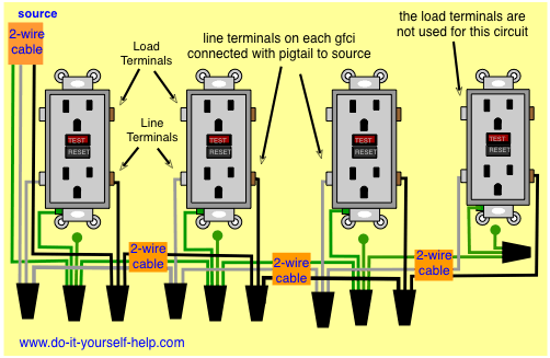
Wiring Multiple Gfci Outlets
Multiple outlet wiring diagram. For wiring in series the terminal screws are the means for passing voltage from one receptacle to another. This repeats until the end of the chain. Wiring a 20 amp 240 volt appliance receptacle. The source for the circuit is at the switch and 2 wire cable runs to each receptacle outlet. This outlet is commonly used for a heavy load such as a large air conditioner. The socket receptacles are usually marked with signs to indicate the position that each wire should go.
To wire multiple outlets follow the circuit diagrams posted in this article. Wiring two outlets in one box in this diagram two duplex receptacle outlets are installed in the same box and wired separately to the source using pigtails spliced to connect the terminals of each one. Understanding switched outlet wiring for home electrical applications the switched outlet wiring configurations show two different wiring scenarios which are most commonly used. With each outlet connected by its own pigtail wire if one fails because of physical damage the other wont be affected and should still work. Multiple outlet in serie wiring diagram. Twist clockwise using pliers then screw a wire cap onto the connection.
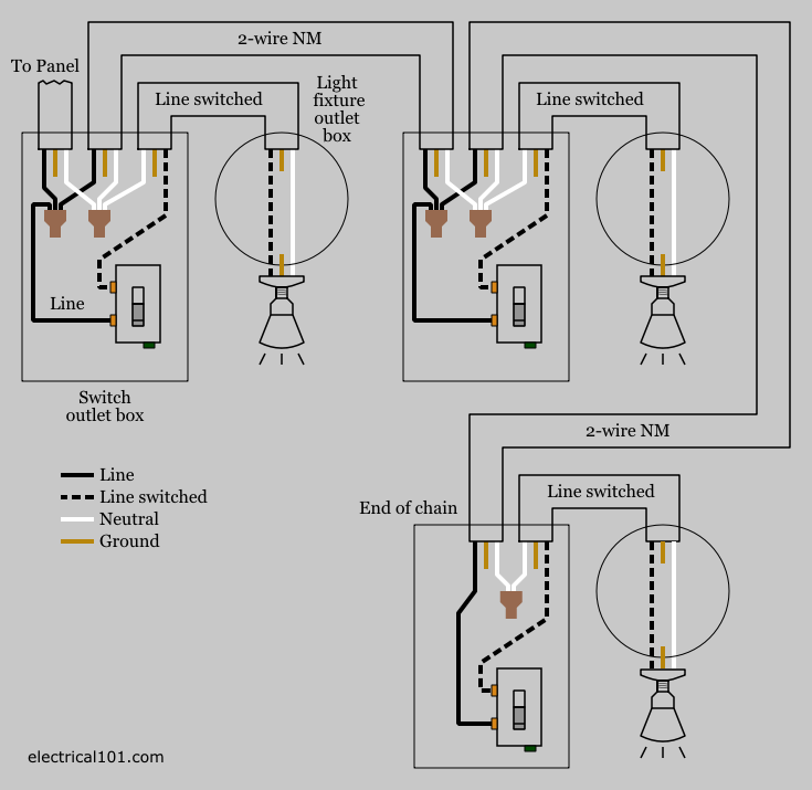
This diagram illustrates the wiring for a split receptacle with the top half controlled by sw1 and the bottom half always hot. Wiring diagram for multiple outlets this diagram shows the wiring for multiple receptacles in an arrangement that connects each individually to the source. This switched outlet electrical wiring diagram shows two scenarios of wiring for a typical half hot outlet that can be used to control a table or floor lamp. Another approach to outlet wiring is to create pigtails. The receptacle is split by breaking the connecting tab between the two brass colored terminals. Wiring diagram for multiple switched outlets.
All wires are spliced to a pigtail which is connected to each device separate from all the others in the row. With this wiring both the black and white wires are used to carry 120 volts each and the white wire is wrapped with electrical tape to label it hot. Right here are a few of the leading drawings we receive from different sources we really hope these pictures will be useful to you as well as hopefully very appropriate to just what you desire concerning the multiple outlet wiring diagram is. In the diagram below a 2 wire nm cable supplies line voltage from the electrical panel to the first receptacle outlet box. The black wire line and white neutral connect to the receptacle terminals and another 2 wire nm that travels to the next receptacle. Wiring multiple outlets diagram gfci wiring diagram multiple size.
You create a pigtail by twisting together multiple wires of the same color its very important that theyre the same color and adding a short length of spare wire of that color. 800 x 600 px source. The outlet should be wired to a dedicated 20 amp240 volt circuit breaker in the service panel using 122 awg cable.
Gallery of Multiple Outlet Wiring Diagram