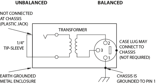
The following is the aes industry standard for balanced audio xlr wiring commonly known as pin 2 hot. It shows the elements of the circuit as simplified forms and the power and also signal connections between the tools.

Xlr Connector Wikipedia
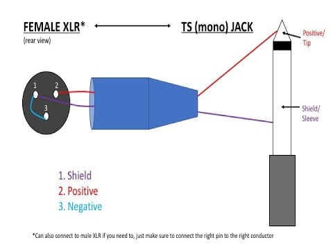
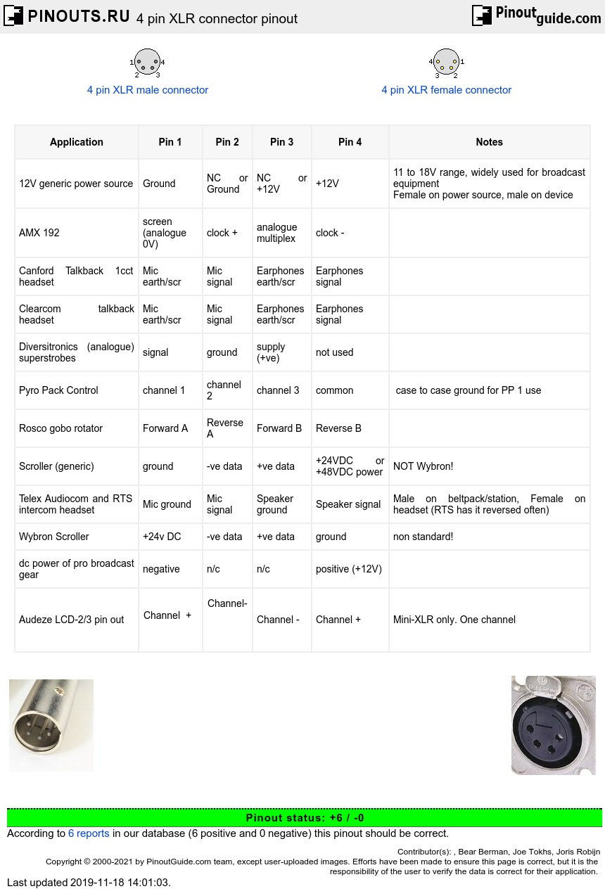
3 pin xlr wiring diagram. The following is the aes industry standard for balanced audio xlr wiring commonly known as pin 2 hot. Collection of xlr wiring diagram pdf. The rear view is the end you solder from here are the connections on each pin. The above diagram shows you the pin numbering for both male and female xlr connectors from the front and the rear view. The above diagram shows you the pin numbering for both male and female xlr connectors from the front and the rear view. Xlr to 14 trs connector wired for balanced mono the usual way to connect a 3 pin xlr to a 14 trs aka stereo jack plug is to use the following pin allocation.
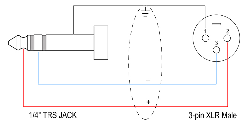
Pinout of professional audio entertainment devices 3 pin xlr connector and layout of 3 pin xlr female connector and 3 pin xlr male connectorthe xlr connectors are used mostly in professional audio and video electronics cabling applications. 3 pin xlr audio pinout. A wiring diagram is a simplified standard photographic depiction of an electric circuit. Xlr 14 wiring connect the xlrs pin 1 to the xlr ground lug and to the 14 ground connect the xlrs pin 3 to the 14 tip. This can be done by either soldering the shield and negative wires of the xlr to the sleeve of the plug. Xlr to 14 mono plug.
3 pin xlr wiring standard. The most comon way to wire a 3 pin xlr to a 14 inch 65mm mono plug sometimes called a jack plug is to join the negative and shield together. Some manufacturers especially in vintage equipment do not follow this standard and instead reverse the polarity of pin 2 and 3. Home audio and video electronics normally use rca connectors. 3 pin xlr microphone wiring diagram. There is no common pinout its depends on application.
3 pin xlr wiring standard 3 pin xlr connectors are standard amongst line level and mic level audio applications.
Gallery of 3 Pin Xlr Wiring Diagram