Attwood marine 500 gph automatic bilge pump 4505 7 in attwood sahara s500 wiring diagram image size 608 x 225 px and to view image details please click the image. 500 gph at open flow 350 gph at 33 head.
Attwood Sahara Series Automatic Bilge Pumps User Manual 2
Sahara s500 bilge pump wiring diagram. Terminal on the ignition switch. Pumps include 36 lengths of 16 gauge caulked and tinned copper wire. Attwood sahara s500 wiring diagram wiring diagram is a simplified enjoyable pictorial representation of an electrical circuit. Don eley professor at the maine maritime ac. It shows the components of the circuit as simplified shapes and the faculty and signal contacts amongst the devices. Here is a picture gallery about attwood sahara s500 wiring diagram complete with the description of the image please find the image you need.
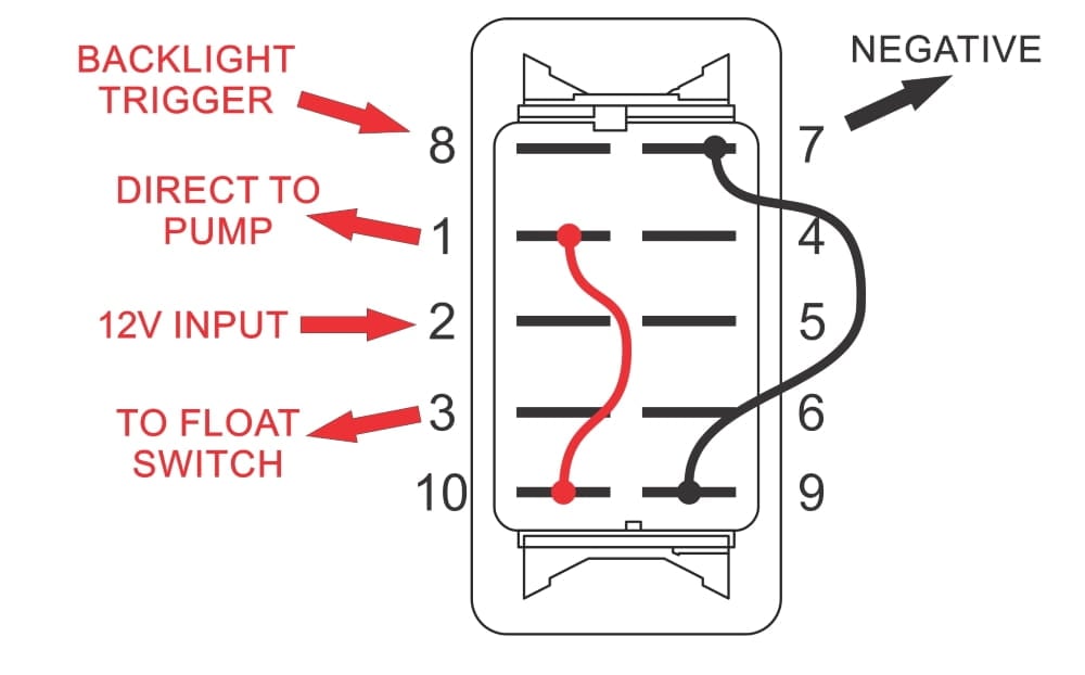
Learn more about how our awesome backlit switches work here even that one is still pretty straight forward though here are some diagrams that show the single jumper required on the back of the switch. 3 backlit bilge rocker switch wiring diagram. The sahara has everything contained in one compact yet durable package pump wire seals strainer and mercury free switch and installs quickly and easily in tight spaces. S500 has plenty of pumping power most jobs. Using butt connectors sized for 16 gauge wire splice fuse holder into positive lead brown between the battery and switch. Attwood sahara s1100 gph automatic bilge pump 4511 1 fo 2709.
Wire connections in a wet bilge need to be sound. Installing a bilge pump can be messy and confusing. See figure 2 2. Feed the switch common from the battery via a fuse or from the batt. Of the three bilge pump switches the only one thats not extremely simple is the backlit automanual bilge pump switch. Route wires out of the way and secure them to the bulkhead to avoid pulling.
Position the pump in the lowest part of the bilge on a flat level surface on the plywood block if it has been installed with the outlet pointing toward the transom. The third terminal will go to the brown with the white tracer for the auto function. The second terminal will go to the on which should be the brown but confirm with your wiring diagram. Using the full length of wire provided and additional wire if necessary connect wires to the pump as shown in the diagram.
Gallery of Sahara S500 Bilge Pump Wiring Diagram