A maximum of 12 poles may be installed on the base. It shows the elements of the circuit as simplified forms as well as the power and also signal connections in between the gadgets.

Ko 8191 Square D Lighting Contactor Wiring Diagram Free Diagram
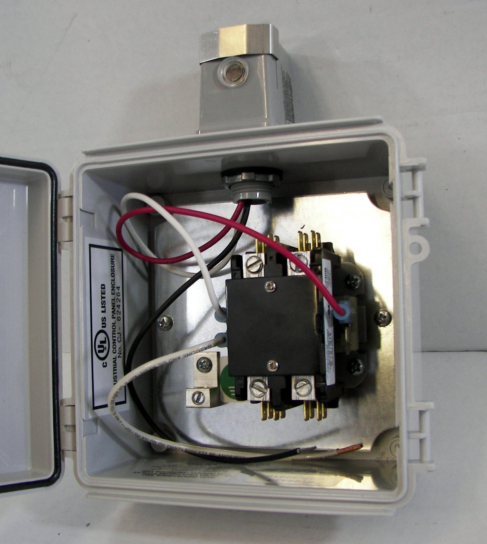
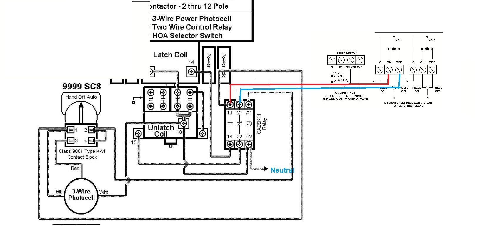
Mechanically held lighting contactor wiring diagram. Electrically held contactors siemens contactor type clm. One type of contactor is an electrically held contactor which is similar to a magnetic starter. Assortment of lighting contactor wiring diagram. These contactors do not change state and disconnect power from the load during a loss of control power whether momentary or sustained. February 16 2019 by larry a. 305 gregson drive cary nc 27511.
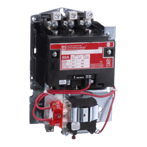
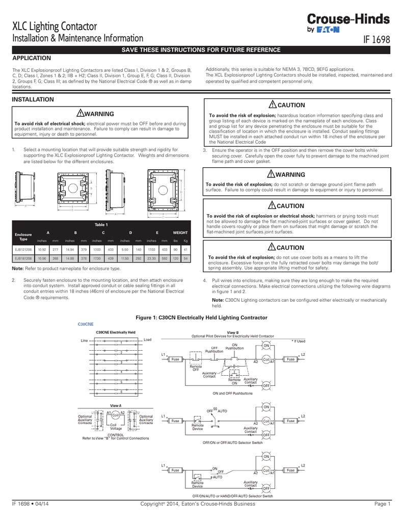
With regard to purchase orders the agreed particulars shall prevail. Lighting contactors mechanically held contactor a two or three wire control module. Square d 8903 lighting contactor wiring diagram diagram 5ab6fcdb9a69 square d 8903 hey mike g ray again what would make a mechanically held in with lighting contactor wiring. Wiring diagrams cr460l electrically held contactor cr460m mechanically held contactor 4 abb inc. Most lighting and heating applications require a contactor to control the loads. Mount lighting contactor in the vertical position only as shown below.
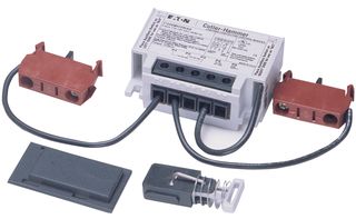
Variety of mechanically held lighting contactor wiring diagram. Siemens class clm cm magnetically and mechanically held lighting contactors are used in applications where it is critical that the contacts remain in the closed position during loss of control power. Low input va permits long wire runs verifies contact status and has built in delays that minimize excessively frequent signals from faulty controllers come in a wide range of input voltages. Four modules cover input voltages from 24 277 vac and 12 24 vdc. It also ensures the removal of coil from the circuit for noise free operation and the elimination of all coil losses. The mechanically held operation ensures that the contactor will not switch to off during control power failure.
Mechanically held lighting contactor wiring diagram. It shows the elements of the circuit as streamlined forms as well as the power as well as signal connections between the tools. The c30cn 30a mechanically held lighting contactors are designed for industrial commercial and outdoor lighting applications where efficient control is required. Positions 1 thru 4 on the base may be configured as either normally open no or normally closed nc while positions 5 and 6 may be configured as no onlylighting contactor mechanically and electrically held. A wiring diagram is a simplified standard pictorial representation of an electrical circuit. A wiring diagram is a simplified standard pictorial depiction of an electric circuit.
Unlike a magnetic starter however a lighting and heating contactor is designed for lighting and resistive.
Gallery of Mechanically Held Lighting Contactor Wiring Diagram