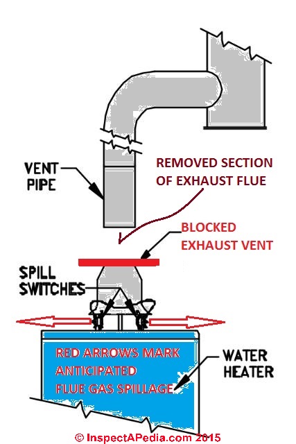
This site is merely. This spilling of carbon monoxide co or extreme heat is detected through a sensor that shuts off gas to the furnace boiler or water heater before enough co is emitted to put the buildings occupants at risk.
Rheem Ruud Gray Furnaceman Furnace Troubleshoot And Repair
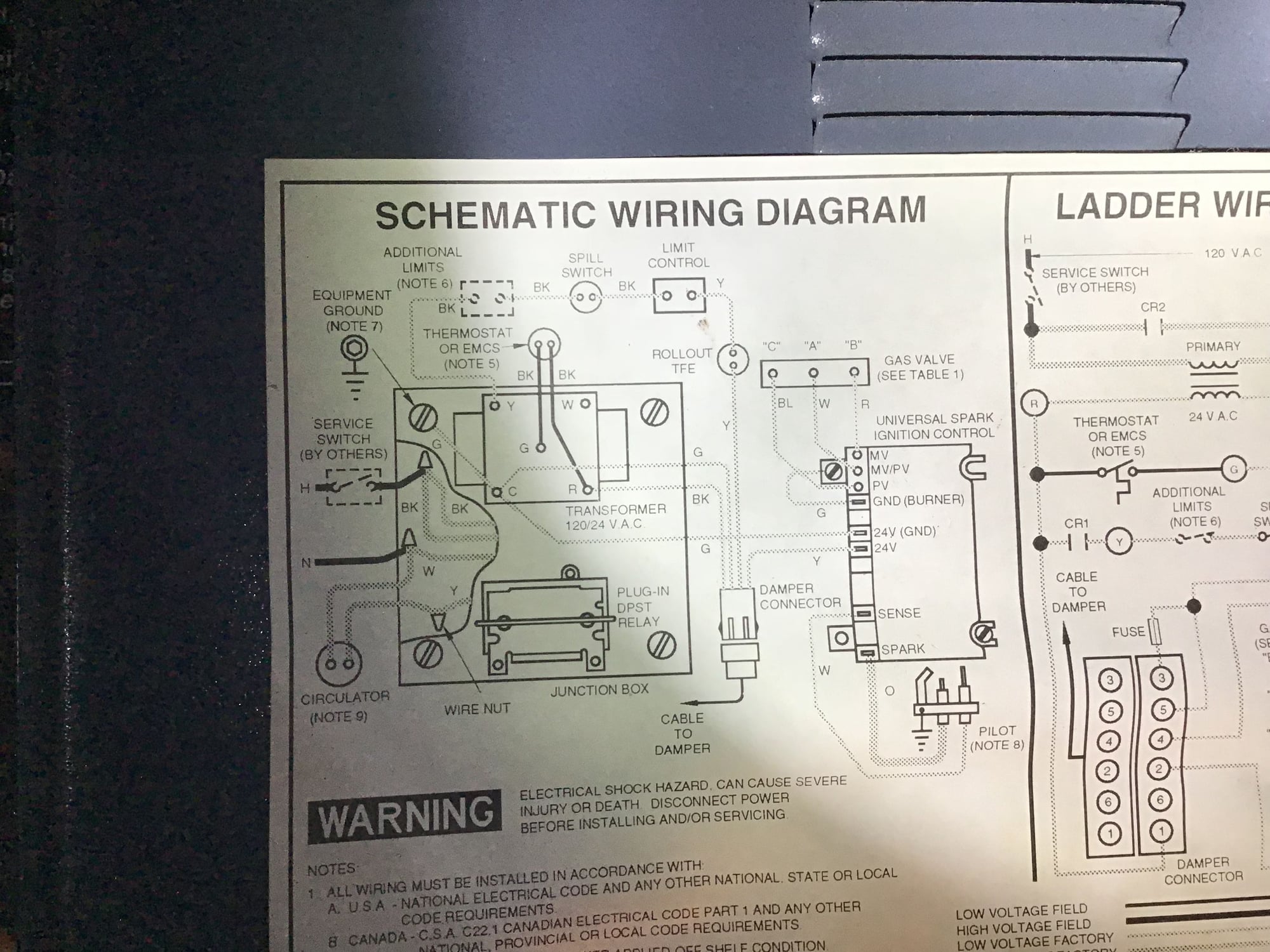
Spill switch wiring diagram. The source is at the sw1 where the hot is connected to. Hey doing it yourself is great but if you are unsure of the advice given or the methods in which to job is done dont do it. Circuit electrical wiring enters the switch box. When wiring this switch you can choose if youd like to illuminate it because of the independent lamp attached to terminals 8 and 7. Wiring lights in parallel with one switch diagram how to wire within how to wire a pull cord light switch diagram image size 500 x 500 px and to view image details please click the image. Gsk 3 spill switch installation manual.
Explanation of wiring diagram 1. A spill switch is a device designed to sense and correct unsafe venting of combustion gases from a gas fired appliance into a building. How to wire a single switch. Here is a picture gallery about how to wire a pull cord light switch diagram complete with the description of the image please find the image you need. 3ø wiring diagrams 1ø wiring diagrams diagram er9 m 3 1 5 9 3 7 11 low speed high speed u1 v1 w1 w2 u2 v2 tk tk thermal overloads two speed stardelta motor switch m 3 0 10v 20v 415v ac 4 20ma outp uts diagram ic2 m 1 240v ac 0 10v outp ut diagram ic3 m 1 0 10v 4 20ma 240v ac outp uts these diagrams are current at the time of publication. 3 way switched outlet wiring.
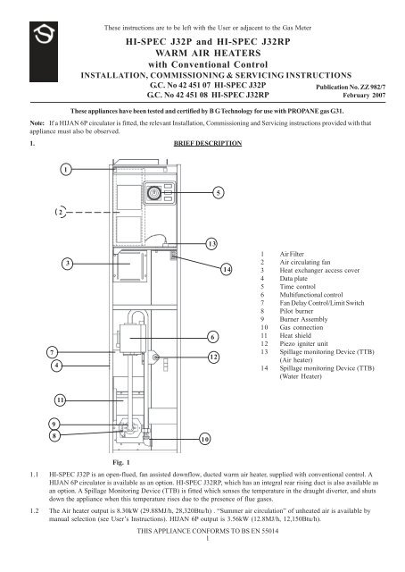
This circuit is wired the same way as the 3 way lights at this link. Spill switch or a set of them can be added to almost any gas fired appliance but it is likely that the gas control valveregulator will need to be replaced too since the old regulator may not have a point to which the spill switchs sensor wire can be connected to tell the valve to close. Installation manual for model gsk 3 spill switch. In this diagram two 3 way switches control a wall receptacle outlet that may be used to control a lamp from two entrances to a room. When wiring a 2 way switch circuit all we want to do is to control the black wire hot wire to turn on and off the load. Mounting location on an mg 1 4 9 barometric draft control.
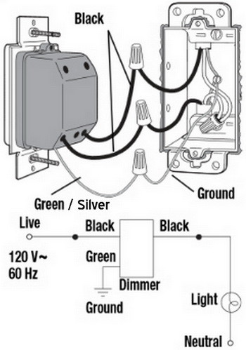
Or these terminals can be ignored for non backlit switch banks. This light switch wiring diagram page will help you to master one of the most basic do it yourself projects around your house. Wiring a single pole light switch. Three wire cable runs between the switches and the outlet. Featuring wiring diagrams for single pole wall switches commonly used in the home. This simple diagram below will give you a better understanding of what this circuit is accomplishing.
Black wire power or hot wire white wire neutral bare copper ground. The wiring diagram to the right will show how to wire and power this 12v 20amp on off on 3 way carling contura rocker switch. Switch wiring shows the power source power in starts at the switch box.
Gallery of Spill Switch Wiring Diagram