Use orange lead for 277 vac. Diagrams for specific situations can be located within this pdf file by using the following methods.

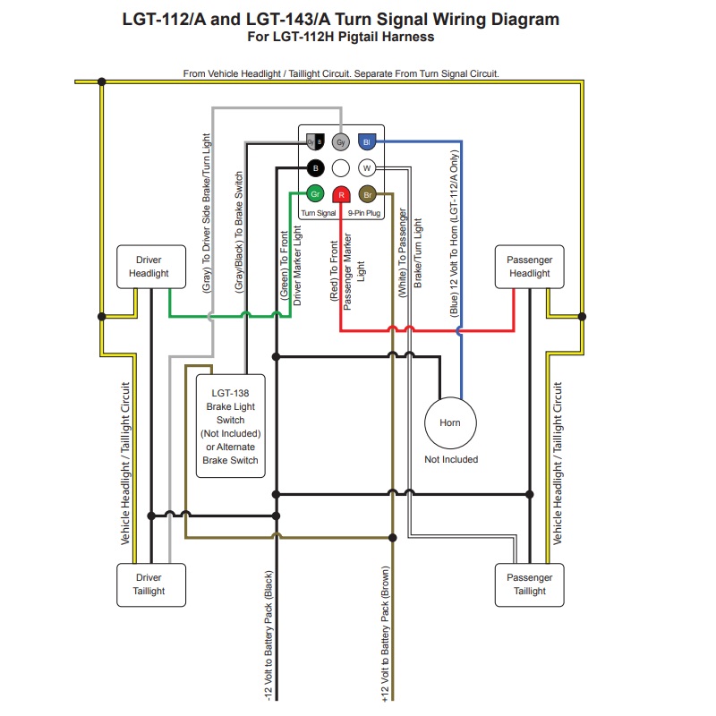
Chevy Cavalier And Pontiac Sunfire 1995 2000 Wiring Diagrams
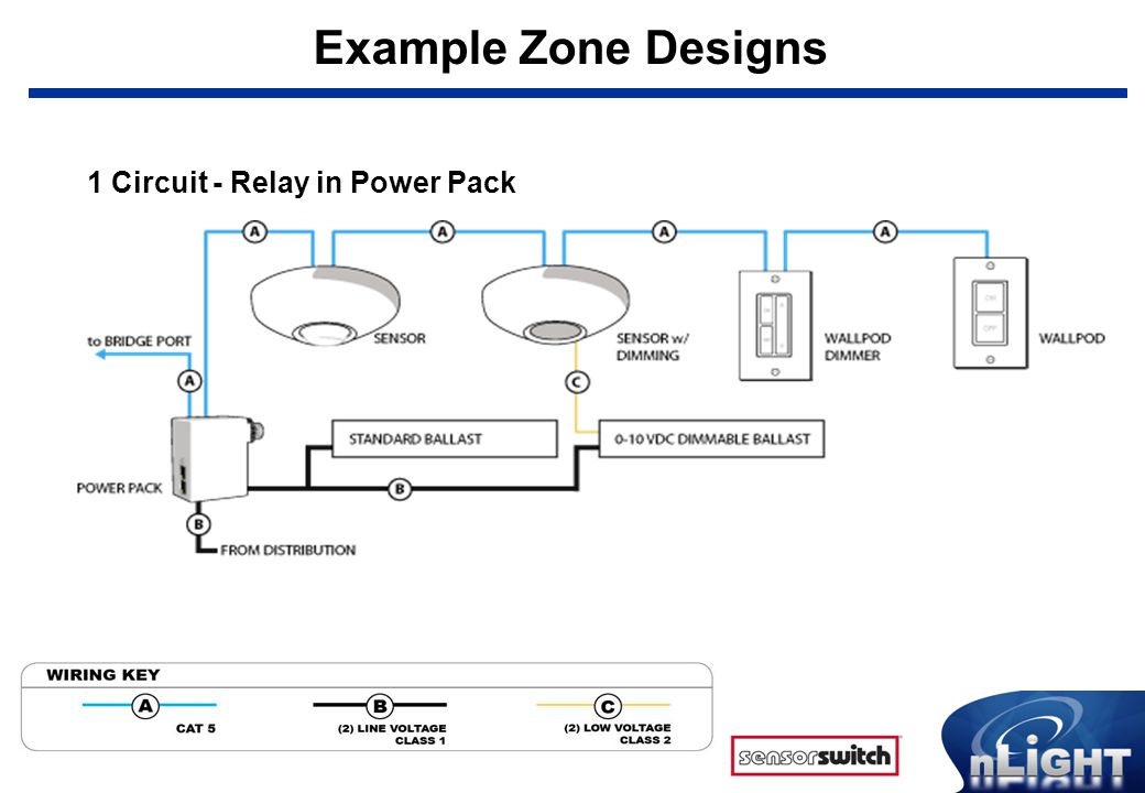
Lighting power pack wiring diagram. After initial wiring is complete check wiring diagram to verify power pack is wired correctly. Wiring diagrams powered by 24vdc supplied by uvpp or uvppm uvpp wiring diagram red black blue power pack contacts rated for 20 amps. The lutron power pack diagram 1 is for use with lutron microos ceiling mounted occupant sensor and lutron 0 10 volt ballast controls. T cap unused lead. Always check local building codes. Load turns off when sensor times out.
Apply power to the circuit. Power packs are the heart of the low voltage sensor system. Power packs wiring diagrams blk 120 v pp20 orn 277 v blk 120 v pp20 orn 277 v. Wiring diagram out of the box functionality upon power up the relay switchpack will be on closed until paired with wireless area controller wac. Improper wiring can cause damage to power pack lighting system and occupancy sensor. One sensor controlling two circuits wiring multiple power packs together blk 120 v pp20 orn 277 v blk 120 v pp20 orn 277 v blk 120 v sp20 orn 277 v blk 120 v.
Use black lead for 120 recommended wire. Output of 0 10v set to 75 light output. When sensor activates load turns on. Utilizing our patented relay circuit protection the pp20 also switches the lighting load on and off. The power pack combines a class 2 15vdc power supply and a heavy duty form a relay. Using power packs to remote sensors blk 120 v.
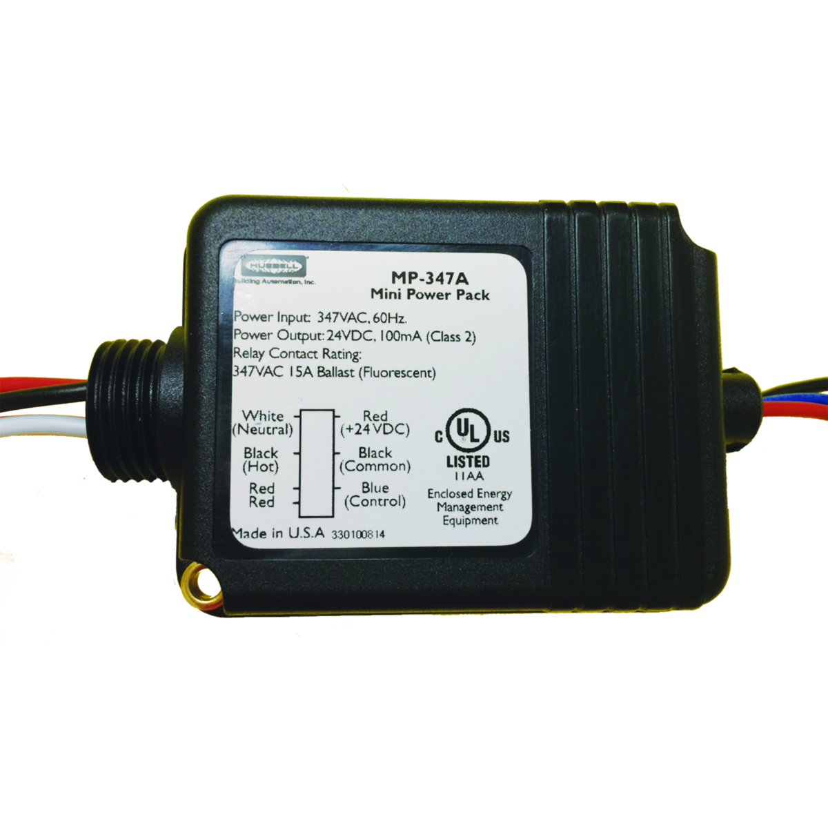
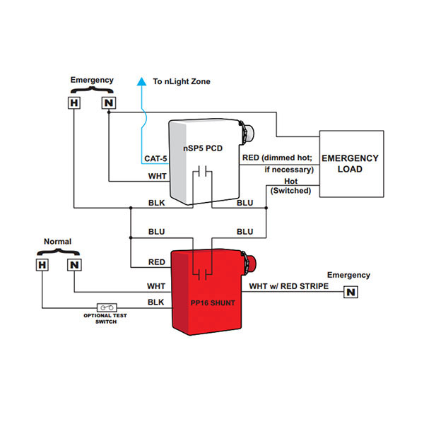
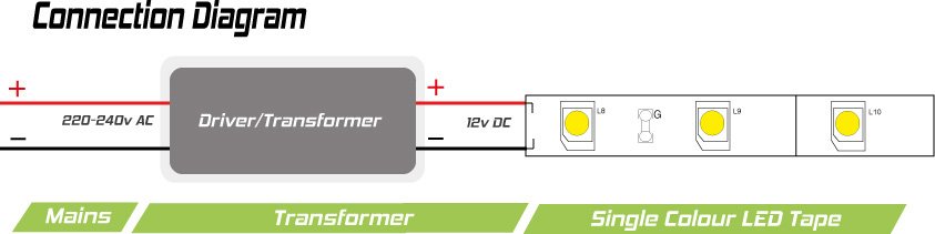
Neutral hot red 24vdc black common blue control red red black white uvppm power pack supplies 150ma hubbell building automation low voltage sensorsdevices requires 33ma each orange manual on override off low voltage momentary switch lighting load ground. Variety of wiring diagram for a power pack pp 20. The pp20 transforms 120 240 or 277 volts to class ii 15 vdc to power the remote sensors. Pp 20 power pack overview power pack installation instructions for use with microos ceiling mounted occupant sensor and. Power pack with 20 amp relay by sensor switch. Most applications require ul listed 18 22 awg 3 conductor class 2 cables for low voltage wiring.
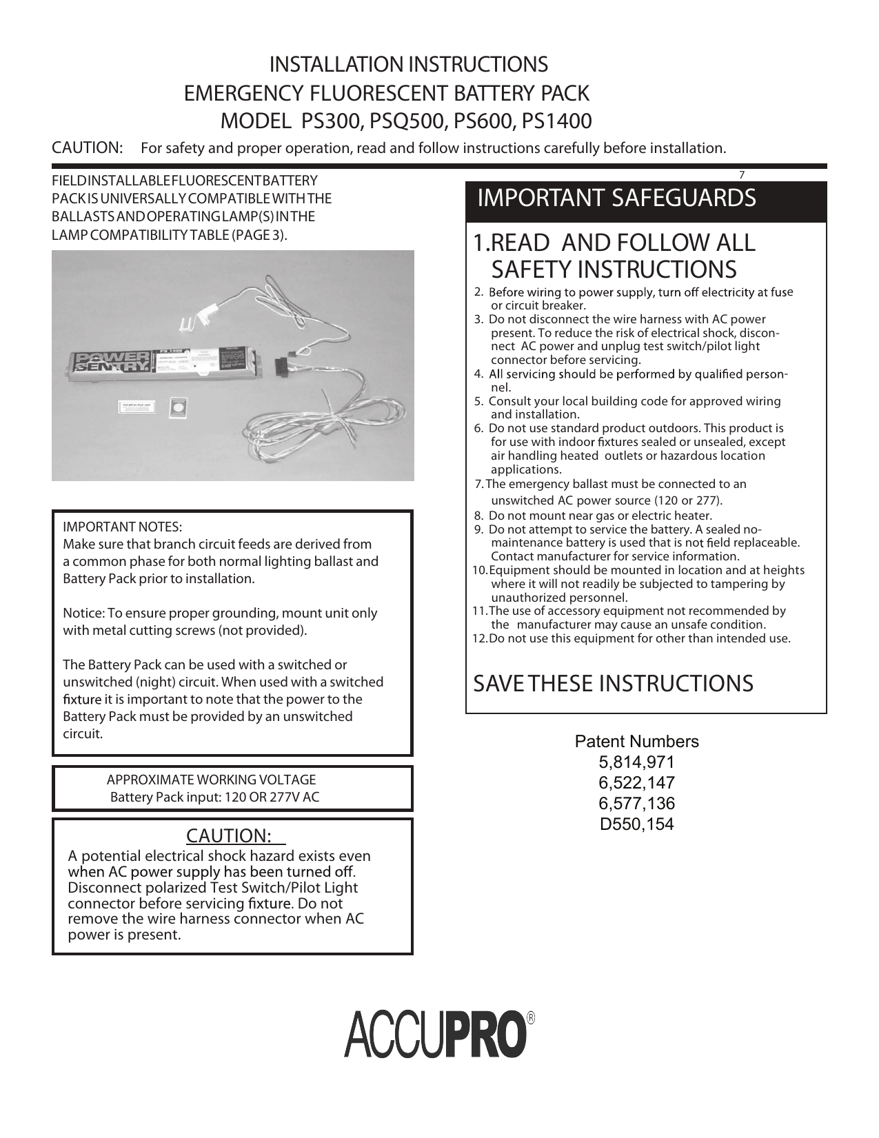
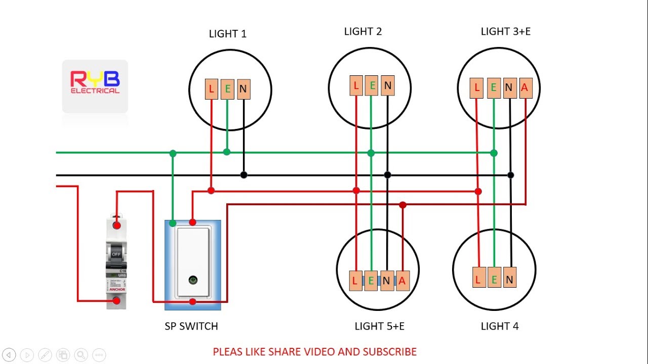
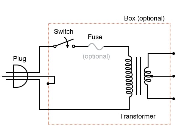
Power packs are designed to attach to existing or new electrical enclosures with 5 12540mmj knockout check electrical codes in your area. 18 3 awg stranded wire shielded or load a nonshielded. A wiring diagram is a streamlined traditional pictorial depiction of an electric circuit. In some cases a specific ballast manu facturer is listed for ac ballasts that have unique wiring arrangements. If a lamp type is not listed the diagram shows a typical straight tube lamp configuration. Low voltage wiring should use at least 22 gauge wire high voltage connections should use at least 14 gauge.
Commissioning button will toggle relay state when button is pressed and released in less than 4 seconds. Line ho white blue switch pack automatic mode operation. Wiring diagrams load blue neutral hot use black lead for 120 vac. It reveals the components of the circuit as streamlined shapes and also the power and also signal links in between the devices.
Gallery of Lighting Power Pack Wiring Diagram