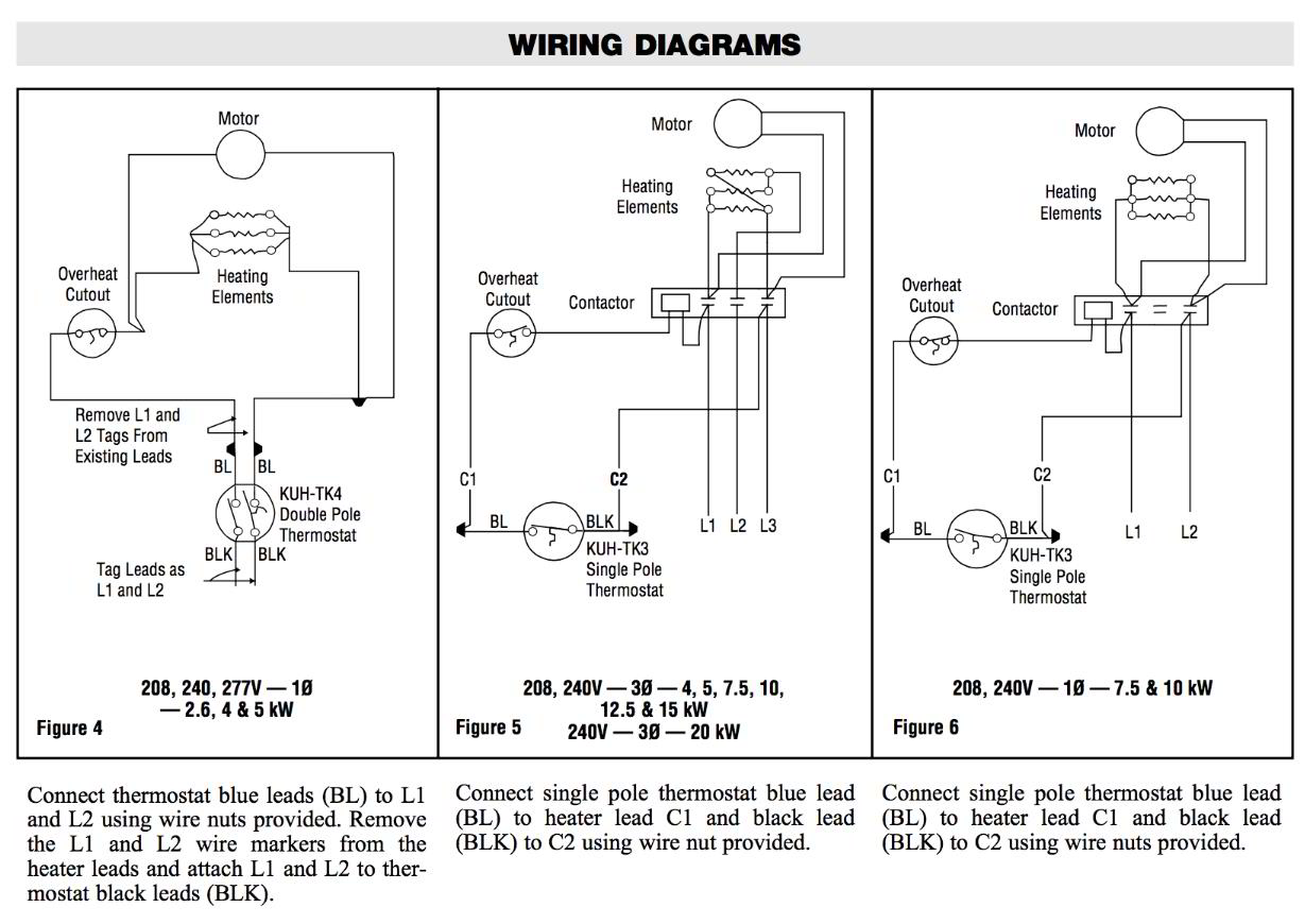
Page 7 wiring continued fes yes 3 phase wiring diagrams fes 1520 3a yes 1520 3a fes 1524 3e yes 1524 3e maximum overcurrent protection 45 amps. Wiring diagrams comprise a couple of things.

8ec78 Quartz Tube Heater Wiring Diagram 240v Wiring Library
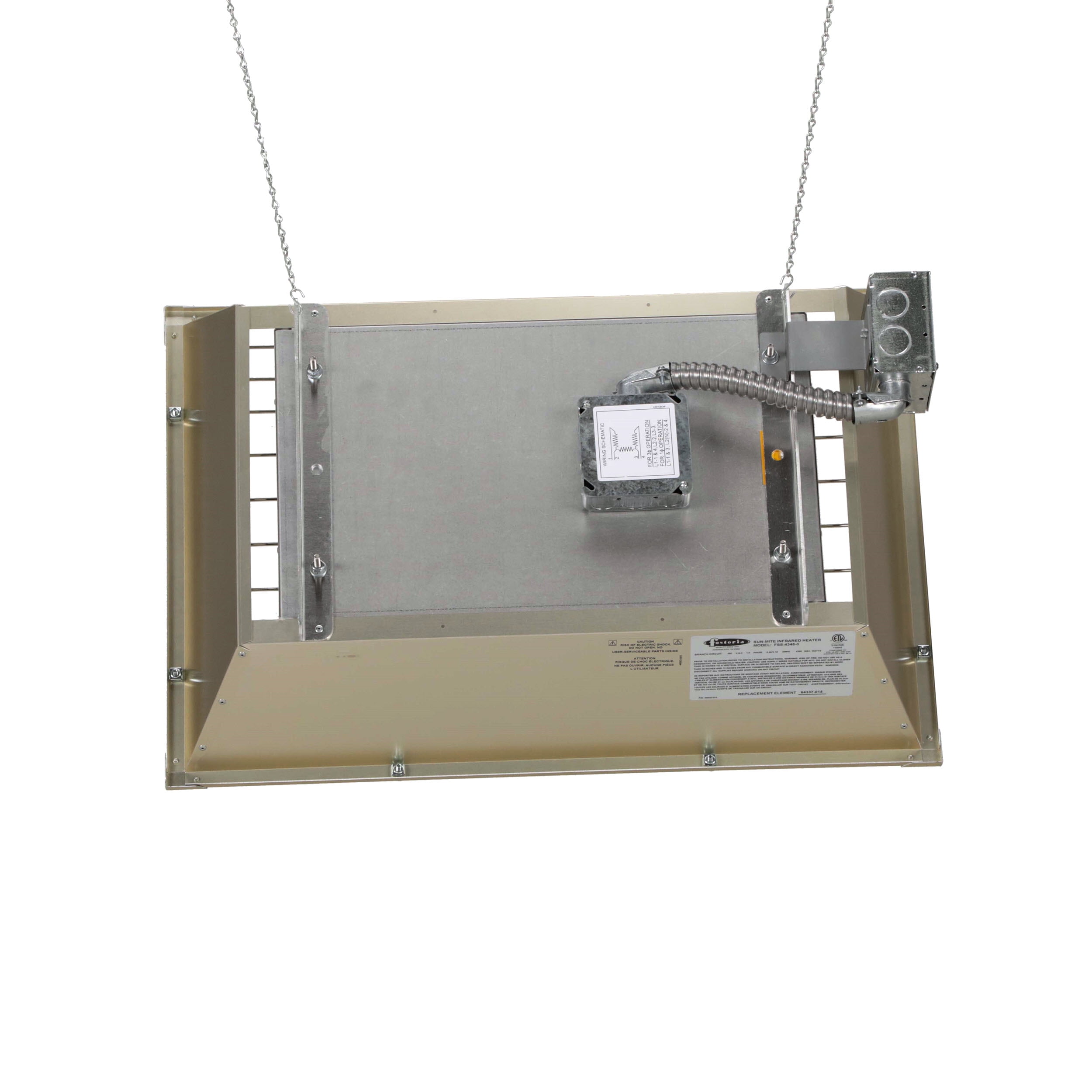
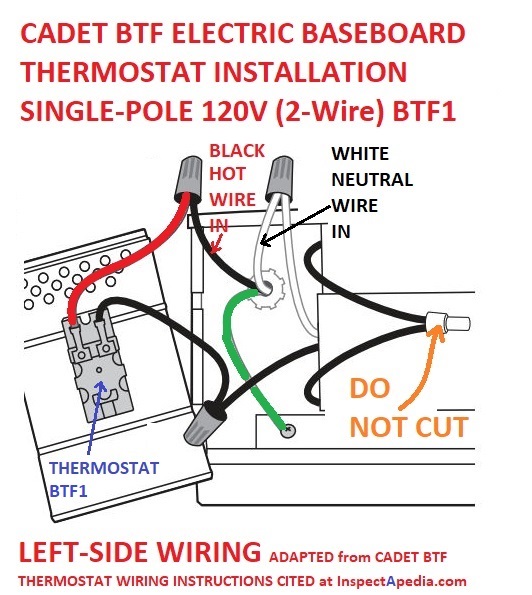
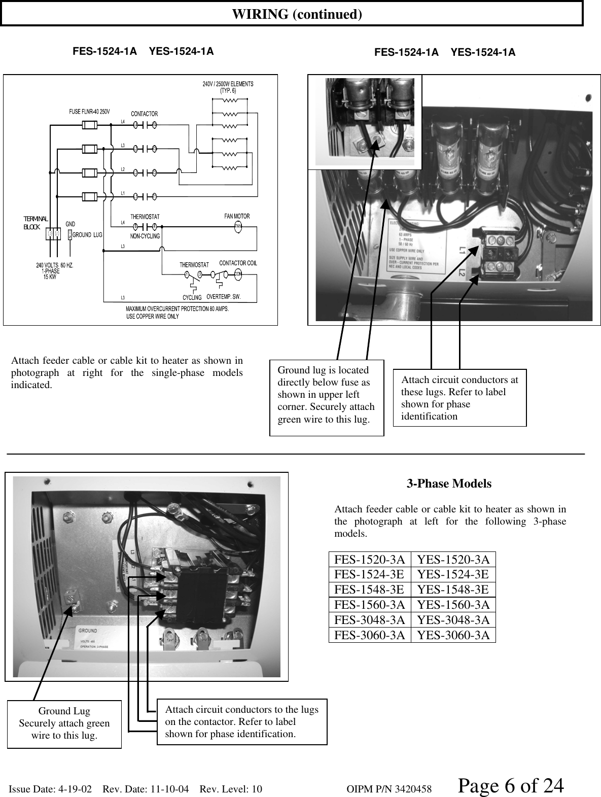
Fostoria heater wiring diagram. Electric heater fostoria e3915 60p user instructions 2 pages summary of contents for fostoria fes 1024 1ca. Assortment of fostoria heater wiring diagram. Also the wire marked h1 and the red wire coming from the heat sink can be. A wiring diagram is a simplified standard photographic depiction of an electric circuit. During installation reference wiring diagram for correct reattachment. Symbols that represent the components in the circuit and lines that represent the connections with shod and non shod.
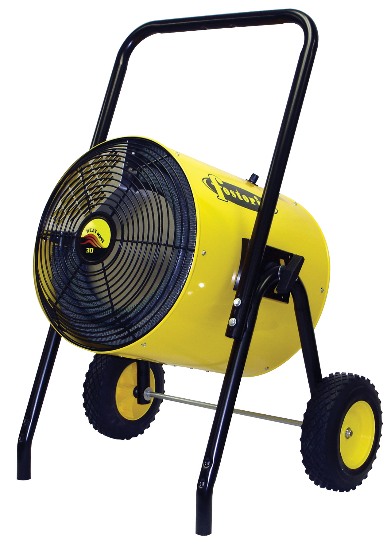
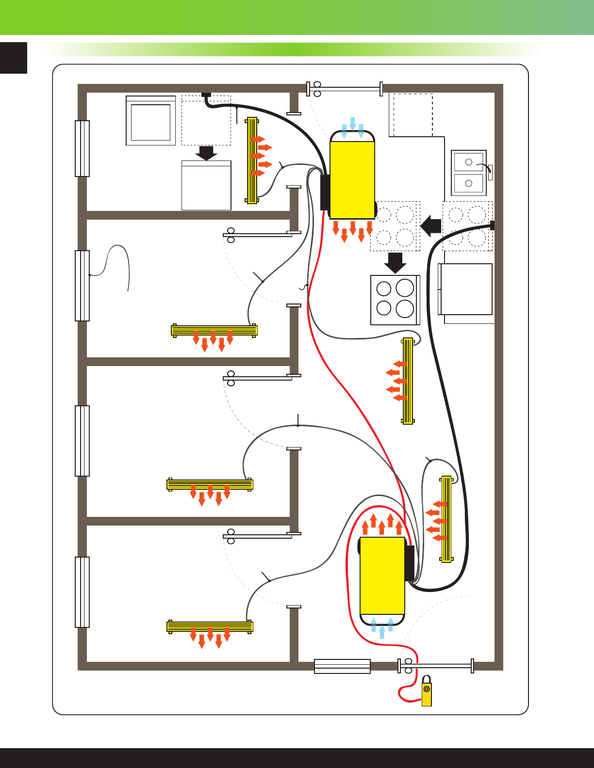
Fostoria heater wiring diagram architectural circuitry diagrams reveal the approximate areas and also interconnections of receptacles lights and also long term electric services in a structure. Heavy duty metal sheath infrared heaters sizing inst allation informa tion metal sheath heaters abc series length wide depth ch 2 26 9 73 ch 4 463 9 73 ch 6 285 199 75 ch 13 505 199 75 ch 27 968 283 149 dimensions in ch 24 kw ch 6 13 27 kw ch 27 kw models the ch 27 series includes 2 terminal box assemblies located on. A wiring diagram is a type of schematic which uses abstract pictorial symbols showing each of the interconnections of components in a very system. Suspended electric heaters description fostoria portable and suspended electric heaters provide clean quiet odor free fan forced heat. Fostoria heater wiring diagram whats wiring diagram. Wire control to power source and heater as shown in wiring diagram using 4 wire nuts provided.
Adjoining wire courses may be revealed around where specific receptacles or components need to be on a typical circuit. Note that wires marked l1 or l2 can be attached to either incoming power lead. Fes yes 3 phase wiring diagrams fes 1548 3e yes 1548 3e fes 1560 3a yes 1560 3a cable not included cable not included maximum overcurrent protection 45 amps. Use copper wire only maximum overcurrent protection 55 amps. It shows the elements of the circuit as streamlined forms and also the power and signal links between the devices.
Gallery of Fostoria Heater Wiring Diagram