Leroy somer avr r448 wiring diagram. Avr 4531 en 22 pmg excitation system with pmg excitation a permanent magnet generator pmg added to the alternator supplies the avr with voltage which is independent of the main alternator winding.

Ee 5113 Wiring Diagram Generator Leroy Somer Wiring Diagram
Leroy somer avr r448 wiring diagram. Using the r726 external module the regulator can control the power factor 2f and can match the alternator. 150v5060hz rated overload current. A wide variety of leroy somer avr r options are available to you leroy somer generator avr r r r r r r. It can be supplied with power either by a power vt or by the arep field excitation system or by a single phase or 3 phase pmg. Leroy somer r automatic voltage regulator download as pdf file pdf text r r avr. Potentiometer p3.
Leroy somer reserves the right to modify the characteristics of its products at any. It is designed to fit as standard on a50 to a54 alternators. Electronic built in overload short circuit and loss of. 12 wires marked t1 to t12. V installation and maintenance. Check whether the st4 jumper or the remote adjustment potentiometer have been connected.
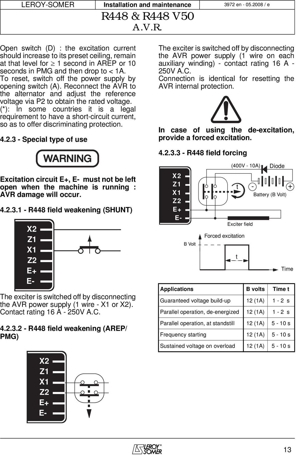
R448 r448 v50 avr. The avr monitors the alternator output. The excitation current the exciter is switched off by disconnecting should increase to its preset ceiling remain the avr power supply 1 wire on each. 2 auxiliary windinqs xix2 and z z2 shunt supply. Optional operating modes. Rotating switch selection 1.
En e. The r449 voltage regulator is of a shunt type. This system provides the machine with a short circuit current capacity of 3 in for 10 s. R448 automatic voltage regulator r448 automatic voltage regulator avr specificationinstallation and adjustments specifications normal avr supply power. R r v avr. Have been made properly as shown in the attached wiring diagram.
Leroy somer 3972 en 052008 e 5 2 supply 21 arep excitation system for both arep pmg excitation systems the alternator voltage regulator is the r 448. Check that the st3 frequency selection jumper is on the correct frequency setting. Page 14 leroy somer installation and maintenance 3972 en 022008 d r448 r448 v50 avr. Potentiometer p1. Open switch d. Potentiometer p2.
Frequency uf function lam function. 31 electrical checks on the avr check that all connections have been made properly as shown in the attached wiring diagram. Warning symbol for general. 23082018 23082018 2 comments on leroy somer avr r448 wiring diagram. The leroy somer manuals are available as free downloads. With arep excitation the r 448 electronic avr is powered by two auxiliary windings which are independent of the voltage match circuit.
Gallery of Leroy Somer Avr R448 Wiring Diagram