Im no electrician and trying to get home wiring circuits to work without pulling any more wire than necessary can leave me feeling way dumber than a series of 2 and 3 wire twisted pairs should. Wiring diagrams used to support the information in accessories equipment are drawn in a top down format.

Charge Controller Wiring Diagram For Diy Wind Turbine Or
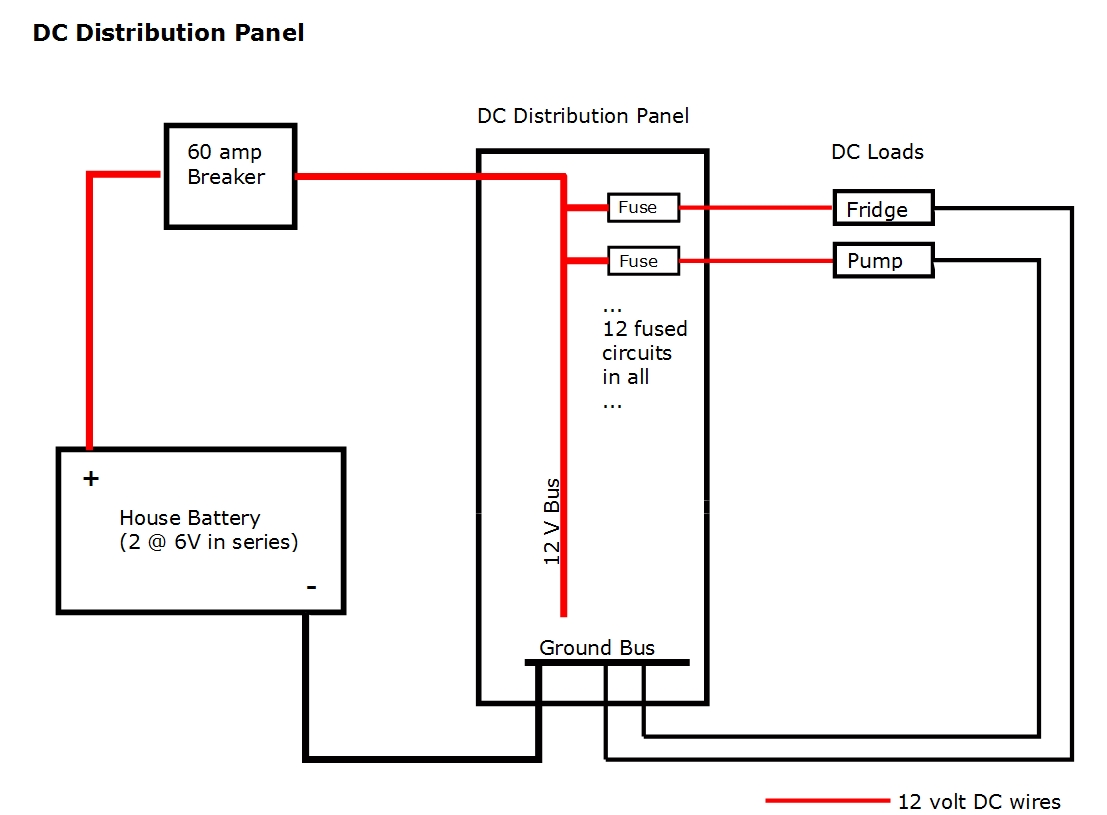
Diy wiring diagram. The diagrams are drawn with the power source at the top of the diagram and the ground point at the bottom of the diagram. For switches and 12 in. A wiring diagram is a simple visual representation of the physical connections and physical layout of an electrical system or circuit. With the light at the beginning middle and end a 3 way dimmer multiple lights controlling a receptacle and troubleshooting tips. Designer 13. Mechanics use car wiring diagrams sometimes referred to as schematics to show them how automotive manufacturers construct circuits.
Component locations are identified on the wiring diagrams. S single switch. First mark the box locations on the studs photo 1 using symbols to indicate outlets switches and lights. S3 three way switch. On this page is a how to video some coworkers and i put together. Wiring diagrams for diy car repairs.
Wiring diagrams for 3 way switches diagrams for 3 way switch circuits including. O duplex receptacle. For outlets or line them up with existing boxes to determine electrical outlet height. Diy home wiring diagram simulation. Mark the height from the floor to the center of the boxes usually 48 in. I dont have a clue.
O light fixture. It shows how the electrical wires are interconnected and can also show where fixtures and components may be connected to the system. In fact a typical service manual will contain dozens of these schematics that can help with proper diagnosis and repair.
Gallery of Diy Wiring Diagram