For 115v connect field. The halon went off to the government for recycling i think.

Fenwal Psd 7125 Manualzz
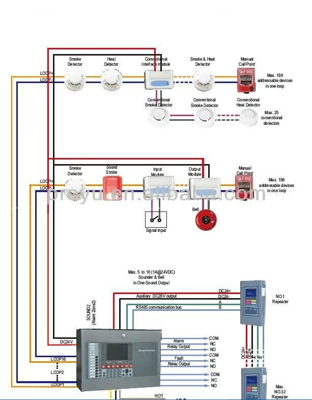
Kidde gemini wiring diagram. The rest of the devices electric realeasing valves nozzles backboxes and all that other stuff is being re used with the potter fm 200 system that the system was replaced with. 34 all system components provided with a key lock feature shall be keyed alike. Featuring a compact and aesthetically pleasing design the gemini ii is ideally suited for modern commercial high tech and industrial applications. It shows the components of the circuit as simplified shapes and the talent and signal associates together with the devices. Since wiring for each protected space is only run a short distance to the local panel. 1x walter kidde halon dump pressure supervisory switch.
Kidde fire suppression system wiring diagram wiring diagram is a simplified conventional pictorial representation of an electrical circuit. They must be familiar and experienced with the wiring diagrams and components electrical installation and familiar not only with nec relevant nfpa and local codes but also trained and qualified by kidde fenwal inc. Kidde fire suppression system wiring diagram gemini ii operating. Architecture with one centrally located panel and inputoutput field wiring running to and from all the protected zones shall not be acceptable. Is a manufacturer of the components that. And configure the kidde aegis.
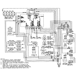
Components description and operation 41 kidde gemini ii main control panel a. Ground screw for field grounding 115v only green wire ground by cook 115v only black wire high speed red wire low speed white wire common for fan power supply connection use 4 wire115v or 3 wire220v cable provided in field wiring box shown on above diagram. Cap off wire that is not in use. It is approved for kidde fm 200 fe 13 and co 2 clean agent systems as well as kidde ind dry chemical.
Gallery of Kidde Gemini Wiring Diagram