According to wiring diagram for a usb joystick you will find just four wires used in the cabletypically it utilizes black black red and white wire colours. Sauer danfoss joystick wiring diagram.

Arcade Control Panel Wiring Diagram Wiring Diagram No Delay
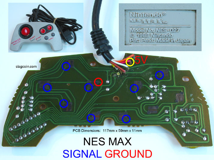
Joystick wiring diagram. A wiring diagram is a simplified standard pictorial representation of an electric circuit. Ground wire to the ground loop and the appropriate jamma wire to the normally open terminal as illustrated. Black wire serves as ground just like in any other apparatus. The ground is usually shared around in the pcb and therefore can be shared among all the signals. Typically it uses black green white and red cable colours. Every joystick and button micro switch must be connected in the same manner.
The red one is to get sure cable with dc ability of 5 liter. June 24 2019 by larry a. Black cable serves as floor exactly like in any other device. If you need any of these functions you will need to solder in your own wire. The red one is for sure wire with dc power of 5 volts. According to usb joystick wiring diagram you will find only four wires used in the cable.
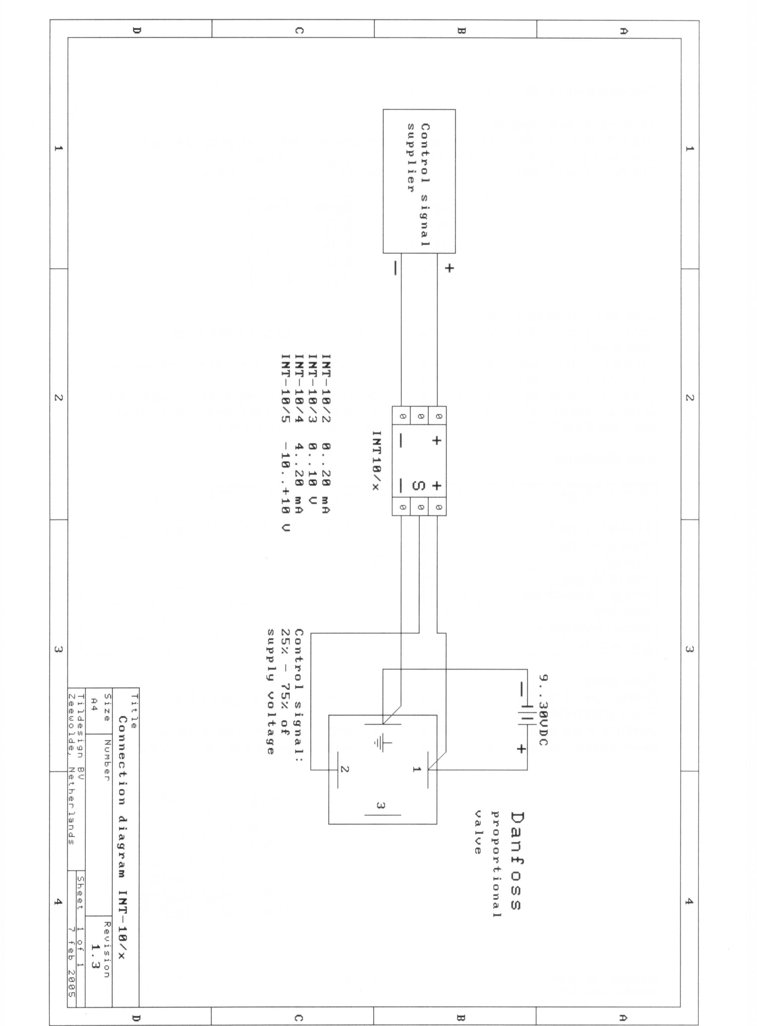
It shows the elements of the circuit as simplified forms and the power and signal connections between the gadgets. When wiring a pcb extracted from a pad controller you need to solder a wire to the signal for each of the needed buttons and one or more wire to each of the unique grounds used by those signals. Collection of sauer danfoss joystick wiring diagram. In the table below x indicates that there is no wire present.
Gallery of Joystick Wiring Diagram