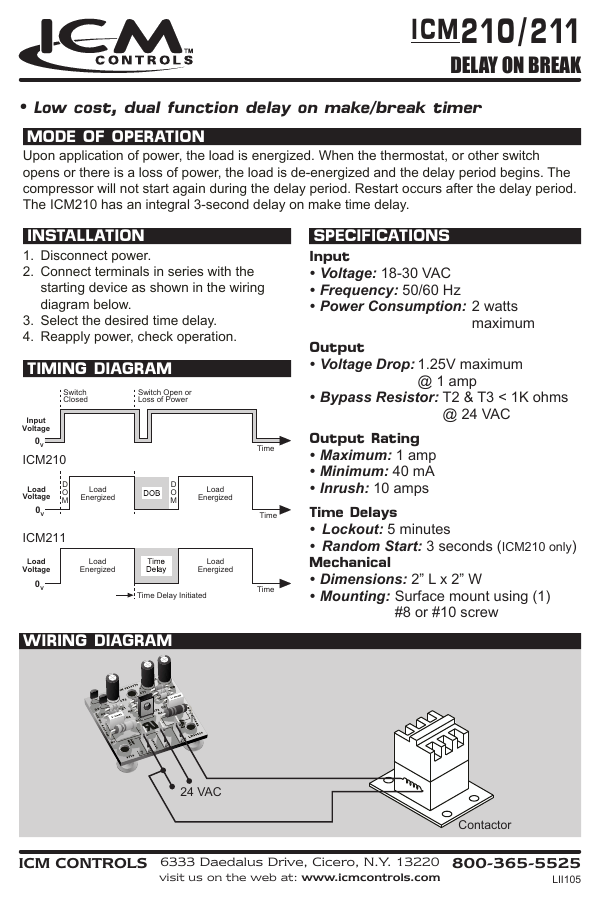
Collection of icm254 wiring diagram. Upon closure of the thermostat the delay on make period begins.

Download Volvo Fl6 Truck Electrical Wiring Diagram Service
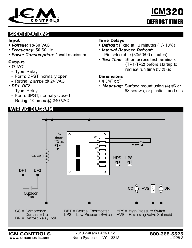
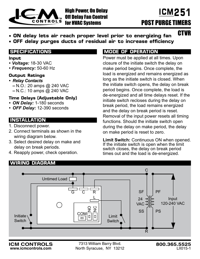
Icm 254 wiring diagram. Mode of operation timing diagram wiring diagram replaces thermal time delays off delay purges ducts of residual air to increase efficiency power must be applied before and during the time delay period. A wiring diagram is a type of schematic which uses abstract pictorial icons to reveal all the interconnections of parts in a system. Mode of operation power must be applied at all times. Select desired delay on make and delay on break periods. Once complete the load is energized and remains energized as long as the initiate switch is closed. Icons that represent the parts in the circuit as well as lines that represent the connections between them.
North syracuse ny 13212 icm controls 8003655525. For the safety and well being of our employees we have made scheduling adjustments and other accommodations to help comply with ny states social distancing policies pursuant to. Connect terminals as shown in the wiring diagram below. When the initiate contact. Wiring diagram control transformer line voltage fan tstat c r g 7313 william barry blvd. Delay on make lets air reach proper level prior to turning on the fan.
Icm controls was granted an exemption from ny states 100 workforce reduction mandate and remains operational. A schematic shows the program and function for an electrical circuit but is not concerned with the physical layout in the wires. Wiring diagrams show how the wires are connected and where they should based in the actual device plus the physical connections between all of the components. Reapply power check operation. Icm254 wiring diagram just whats wiring diagram. A wiring diagram is a simplified traditional pictorial representation of an electrical circuit.
Timing diagram 3 or 5 minute fixed or 10 minute adjustable delay works with anticipator thermostats icm2 ˆˇ 0c4m56 n 0 n 0 stal 0c4m56 ˇ wiring diagram tstat contactor compressor control transformer line voltage 7313 william barry blvd. Once complete the load is energized and remains energized as long as the initiate switch is closed. Icm controls icm254 icm254 fan blower control dual onoff delay timer adjustable time delay controls the circulating fan in heat pump air conditioning and forced air systems. Reapply power check operation. Select desired delay on make and delay on break periods. It shows the components of the circuit as simplified shapes and also the power and also signal links between the devices.
Wiring diagrams are made up of two things. Off delay timing function continues to run the fan at the end of the heatingcooling cycle thereby purging ducts of residual air and. Mode of operation power must be applied at all times. Click here to read the official exemption notice. Reapply power check operation. How is really a wiring diagram different from the schematic.
Upon closure of the thermostat the delay on make period begins.
Gallery of Icm 254 Wiring Diagram