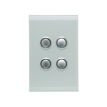
This video outlines the key features of the range and demonstrates how to install clipsal iconic switches and sockets. The iconic range includes a number of modular electronic switches dimmers and timerstimeclocks incorporating advanced remote load control technology with multi way dimmingswitching capabilities.

Bb 0699 Clipsal 2000 Light Switch Wiring Diagram Together
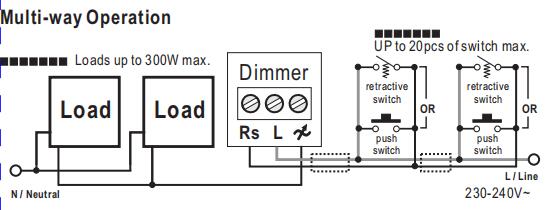
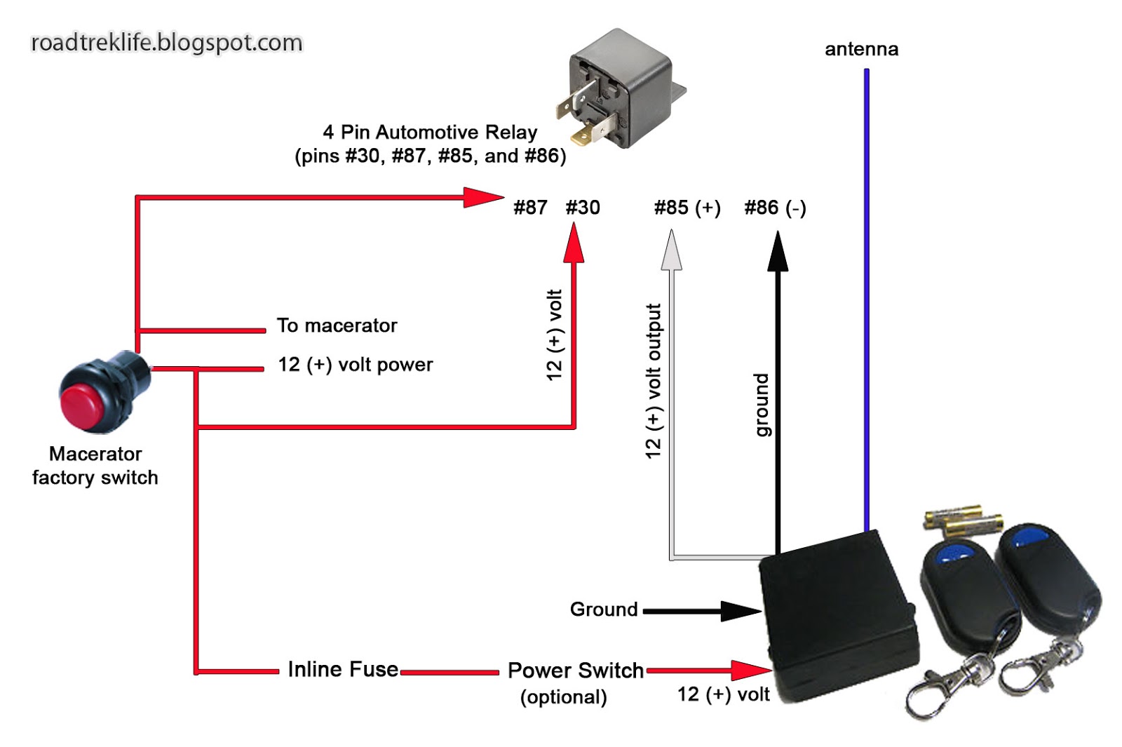
Clipsal iconic led wiring diagram. The controllink pushbutton cannot be used to place a connected iconic. 51 led indicator iconic pushbutton units do not have led indicators. 26 106 wiring diagram. Discover the brand new clipsal iconic wiring devices range. Hot water service booster application 31vber alternative 27. 27 107 wiring diagram.
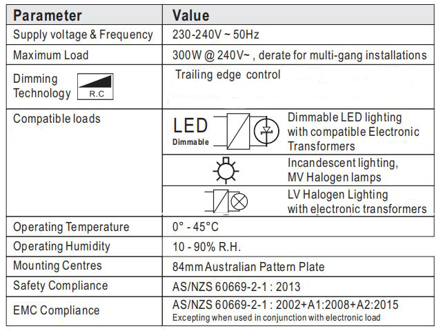
Iconic pushbutton electronic switch timer timeclock installation instructions caution equipment damage hazard install the device according to instructions in this document. View the 40mledw product features specifications documents and related faqs. 25 105 wiring diagram. Do not use this product for any other purpose than specified in this. Pay attention to the specifications and wiring diagrams related to the installation. The clipsal iconic range includes a number of modular electronic switches dim.
11 91 connection limitations. 2 wire 350 w units. Clipsal iconic led module 250v pack of 10.
Gallery of Clipsal Iconic Led Wiring Diagram