According to earlier the traces in a 7 way plug wiring diagram represents wires. But it does not imply link between the wires.
Bd3cbea Curt Trailer Wiring Diagram 58141 Wiring Library
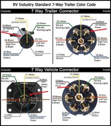
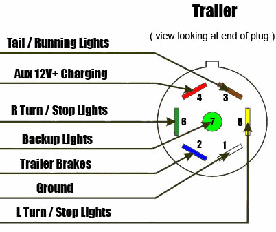
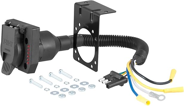
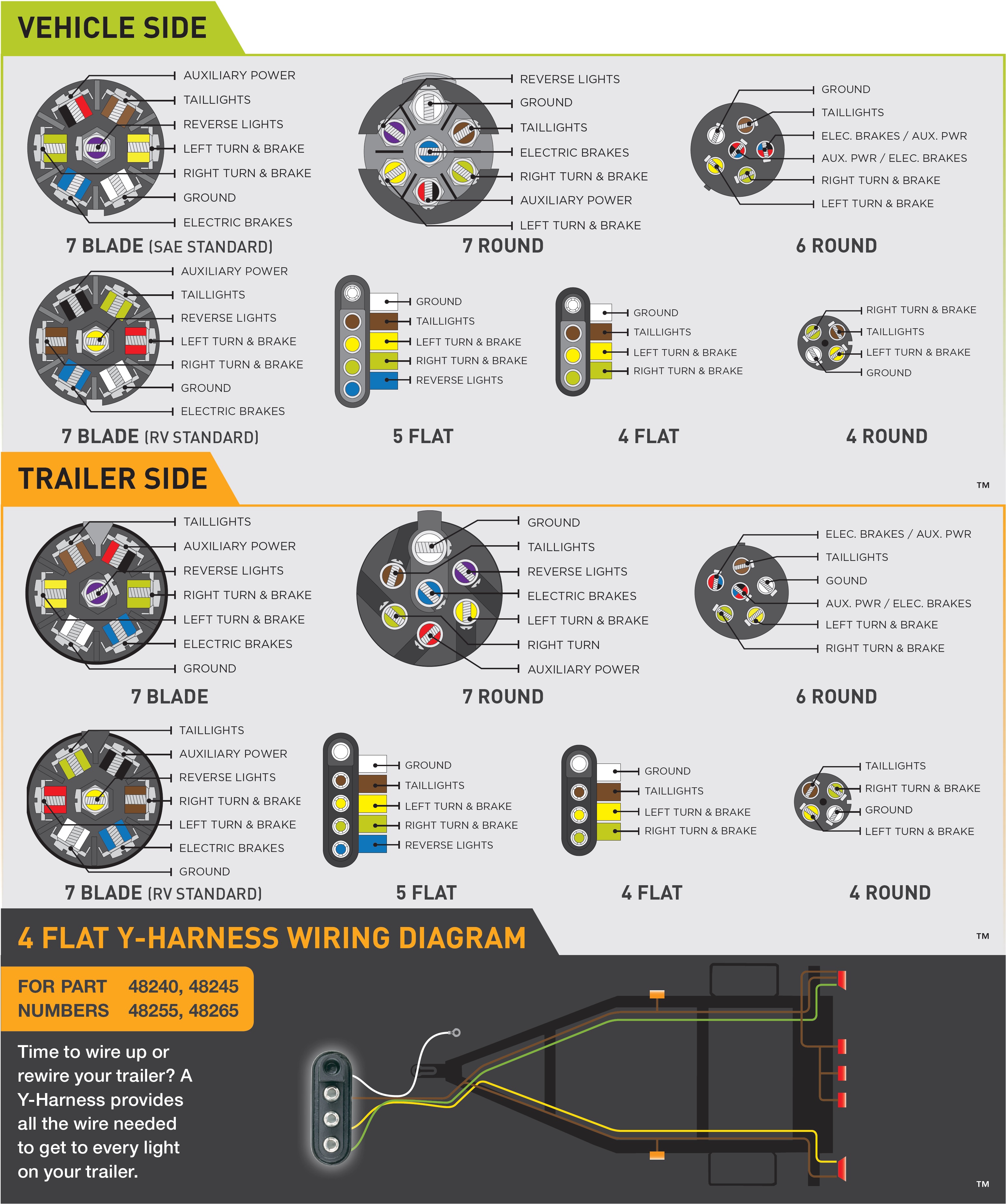
Curt 7 way plug wiring diagram. Select vehicles come with a standardized uscar socket that provides a connection point for a curt oe wiring harness. The yellow wire is the center pole of the 7 way connector and is normally used for connection to the reverse light circuit. Like a t connector an original equipment wiring harness plugs into the uscar socket without any cutting splicing or soldering required and it provides a standard trailer wiring output such as a 4 way flat or 7 way rv blade. Tm park light green battery feed black rt right turnbrake light brown lt left turnbrake light red s trailer electric brakes blue gd ground white a accessory yellow this is the most common standard wiring scheme for rv plugs and the one used by major auto manufacturers today. 7 way plugs and sockets are typically used on larger trailers for heavy duty towing such as on gooseneck and 5th wheel trailers as well as larger utility trailers and boat trailers. It can transfer power better therefore the connector is suggested for higher level electric in the auto.
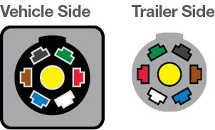
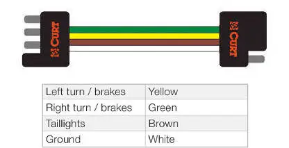
Here is the diagram for 7 pin connector. White pin to your ground. Occasionally the cables will cross. The wiring for the adapter 4 pole to 7 pole and 4 pole item c57674 is wired as followsthe white wire is grounded to the vehicle frame as you have indicated. Curt 7 way connectors are designed to supply power to the trailers taillights turn signals brake lights electric trailer brakes reverse lights auxiliary power and ground connection. Injunction of 2 wires is usually indicated by black dot to the junction of 2 lines.
This curt 7 way trailer wiring diagram model is much more suitable for sophisticated trailers and rvs. 7 way plug wiring diagram standard wiring post purpose wire color.
Gallery of Curt 7 Way Plug Wiring Diagram