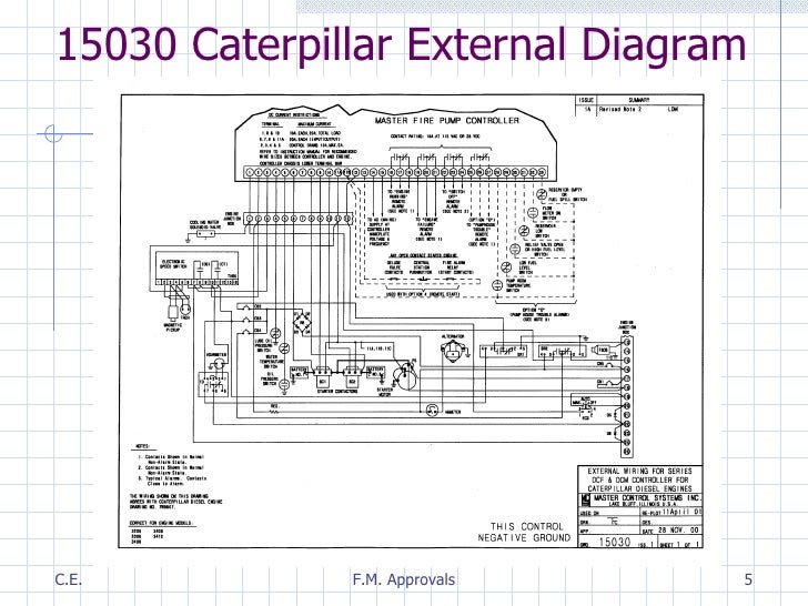
All controllers you use in a fire pump system have to be suitable for use as service equipment per sec. A wiring diagram is a simplified traditional photographic depiction of an electric circuit.

Ef35a Pool Pool Pump Wiring Diagrams With Timing Light
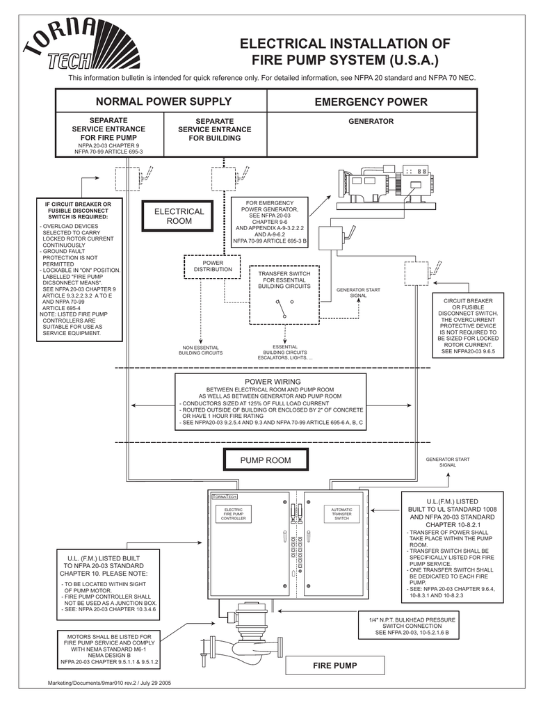
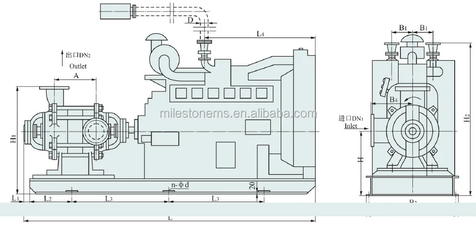
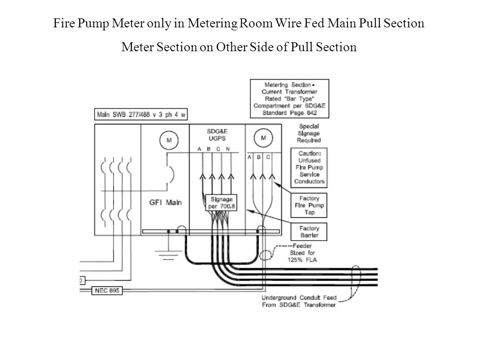
Fire pump wiring diagram. Discuss the variables that impact the layout of a fire pump and how they are addressed. Describe the steps necessary for appropriately sizing a fire pump. Here is a picture gallery about fire pump wiring diagram complete with the description of the image please find the image you need. It shows the parts of the circuit as simplified shapes as well as the power as well as signal links between the devices. Keep fire pump supply wires on the load side of the final disconnect and overcurrent protection entirely independent of all other wiring. A wiring diagram is a simplified standard pictorial representation of an electric circuit.
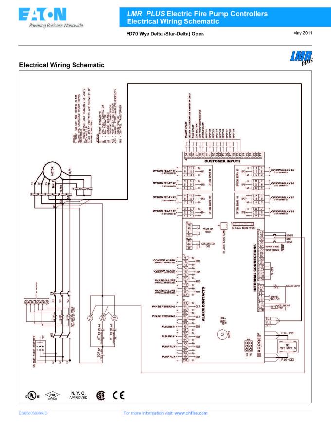
7 124 in nfpa 20. Article 695 provides other requirements intended to protect these wires from damage from fire structural failure or operational accident. That apply to sizing and layout of fire pumps. Where the disconnecting means disconnects the fire pump motors its accessories and the plant loads it shall be capable of disconnecting the sum of the locked rotor current of such loads. Wellborn collection of fire pump controller wiring diagram. Identify the components of a fire pump and driver.
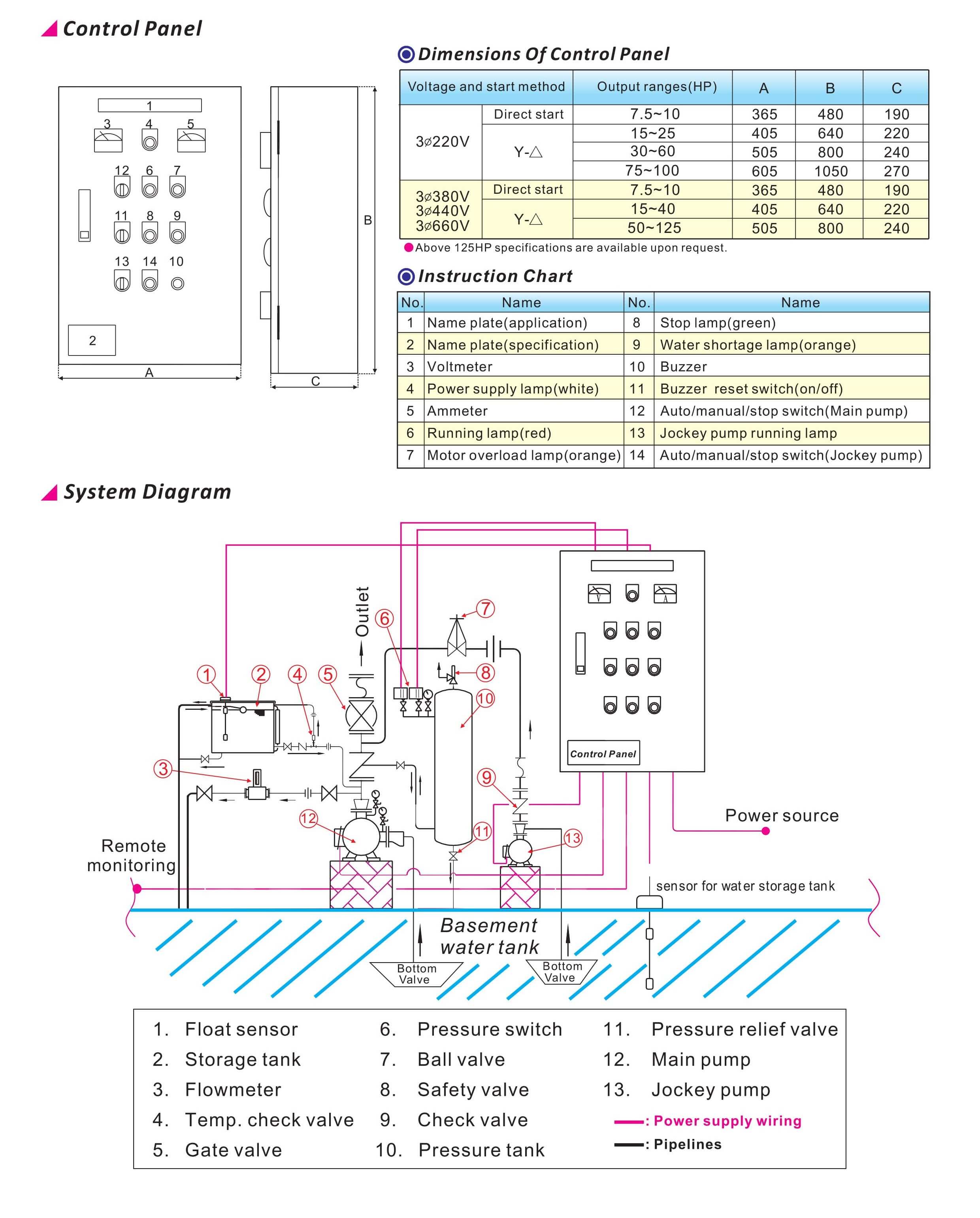
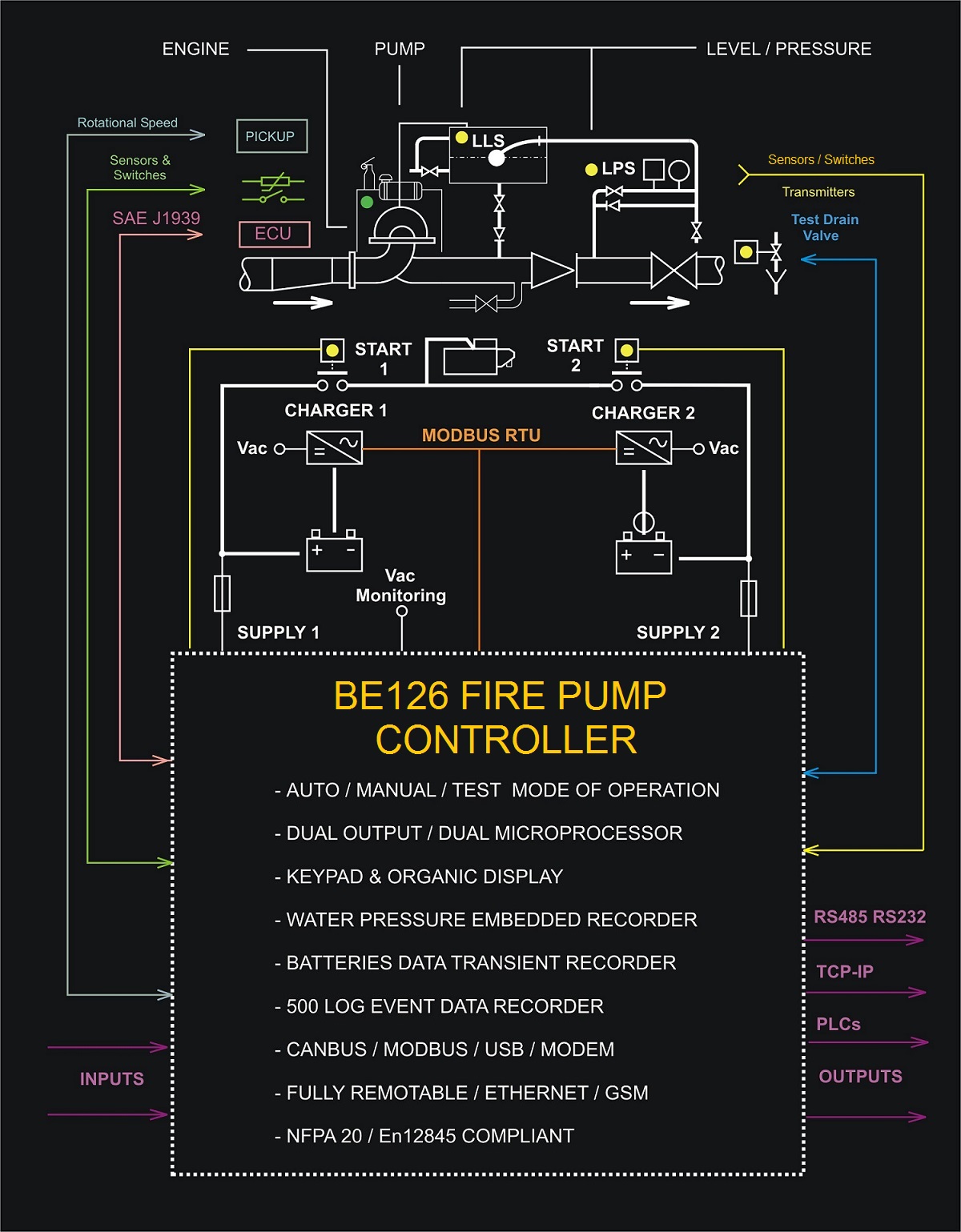
Describe the purpose of the various components of a fire pump and driver. August 16 2018 by larry a. It reveals the elements of the circuit as simplified shapes and the power as well as signal links between the tools. Fire and jockey pump controller sensing lines mike trumbature with regard to fire pump wiring diagram image size 797 x 612 px and to view image details please click the image. Assortment of pump control panel wiring diagram schematic.
Gallery of Fire Pump Wiring Diagram