Flexible conduit and connectors are included in our vent system wiring kit or can be purchased separately. Verify input power voltage before connecting to starters or contactors.

Zw 1742 Exhaust Fan Kitchen Furthermore Exhaust Fan And
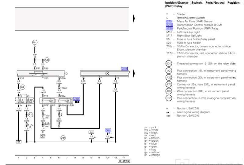
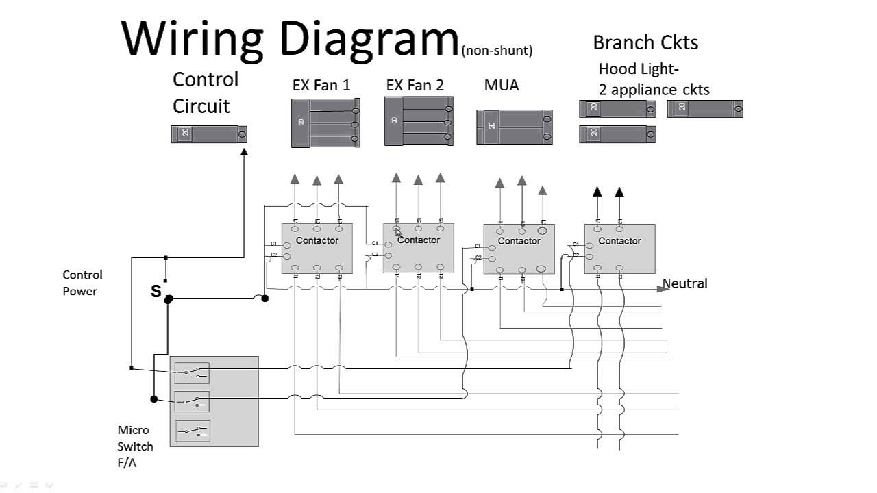
Exhaust fan interlock wiring diagram. If not recheck each wire connection carefully. 3interlock relay installation completion once the wiring is completed turn on the electrical power to the furnace plug the ventilation unit and verify if the relay is working properly. On some newer homes ive seen there is a switch in the hallway that somehow is wired in with the fan and furnace. Thanks for any replies. Table 1kit contents part. But i was told is the new code in alberta canada.
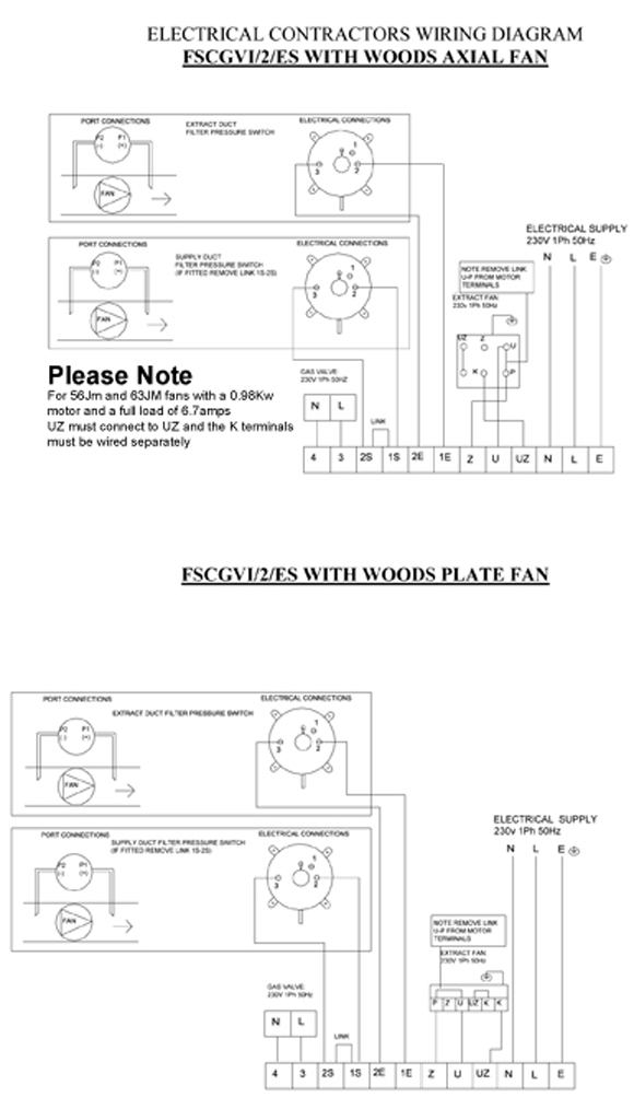
Nov 16 2015 wiring for a ceiling exhaust fan and light. Exhaust fan intake shutter dimensions form. Do i have to interlock all the bathroom fans with the furnace. I am wondering what wire guage to use and how i can interlock the bathroom fan with the furnace so when fan for bathroom is switched on the furnace starts. Afcs wiring diagram list the proper phase voltage and amp load. Check rotation of fans exhaust fans will move some air in reverse see rotation arrow on fan.
To correct rotation of fans reverse any two leads from the 3 phase starter to the fan. Any ideas on this. 14 gauge or thicker wire is recommend when wiring the fan and any other venting supplies purchased from us. Nov 16 2015 wiring for a ceiling exhaust fan and light. What is the correct way to wire the fan and furnace in a new home. Wiring diagrams for a ceiling fan and light kit.
When the ventilation unit is on the furnace blower should also operate. Detailed coloured12n trailer wiring diagram which is commonly used on uk and european trailers and caravans from western towing. First i do not know the reason behind this since this bathroom fan exhaust to the outside ducted to the outside. How do i determine what is the principal exhaust fan. 3ø wiring diagrams 1ø wiring diagrams diagram er9 m 3 1 5 9 3 7 11 low speed high speed u1 v1 w1 w2 u2 v2 tk tk thermal overloads two speed stardelta motor switch m 3 0 10v 20v 415v ac 4 20ma outp uts diagram ic2 m 1 240v ac 0 10v outp ut diagram ic3 m 1 0 10v 4 20ma 240v ac outp uts these diagrams are current at the time of publication.
Gallery of Exhaust Fan Interlock Wiring Diagram