Euromap technical co vdma fv kug lyoner str. A current of at least 6 ma must be maintained during signalling.

Buy Euro Map 67 Interface Sprue Picker For Order Euro Map 67
Euromap 67 wiring diagram. Occasionally we may have to slightly customize design color or even accessories. Euromap 67 wiring diagram. Euromap 73 version 11 euromap 73 page 6 of 8 232 table 2. All psi harnesses are made in the usa. Euromap 67 wiring diagram wiring diagram is a simplified satisfactory pictorial representation of an electrical circuit. Plug on the injection moulding machine male contact no male see fig.
The maximum current is 6a. Euromap 67 wiring diagram. The cts v had two pins cpp switch and cruise control switch which showed on the wiring diagram to be coming from the cruise control system but it doesnt show the resumeaccel or set coast inputs. A7a12 spare not fixed by euromap manufacturer dependent. Euromap 67 version 111 euromap 67 page 4 of 9 22 contact specification 221 emergency stop safety devices mould area free the voltages of the signals must not exceed 50 v dc or 250 v ac. Euromap technical co vdma fv kug lyoner str.
However see also. Bench harness wiring diagrams. In addition recommendations are given for signal voltage and current levels. 24 sources of supply. 2 contact name signal designation description a1 a6 spare reserved for future use of euromap. This is intended to provide interchangeability.
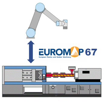
Euromap 67 draft 110version 19 euromap 67 page 3 of 10 1 scope and application this euromap recommendation defines the connection between the injection moulding machine and the handling device robot. Wed like a new idea for it then one of them is euromap 67 wiring diagram. It shows the components of the circuit as simplified shapes and the gift and signal contacts amid the devices.
Gallery of Euromap 67 Wiring Diagram