All information is subject to change without any notice. Euromap 12 robot euromap 12 shall therefore only be applied for replacement purposes onin the us.
Abb Irc5 Controller
Euromap 67 to 12 wiring diagram. Euromap 12 wiring diagram reserved for future use of euromap. A wiring diagram usually gives assistance nearly the relative slant and bargain of devices and terminals upon the devices to back up in building or servicing. 23 plug contact assignment. An identical text of euromap 63 is published as an spi document. If you want to find the other picture or article about euromap 67 wiring diagram estop wiring. Euromap 67 wiring diagram wiring diagram is a simplified satisfactory pictorial representation of an electrical circuitit shows the components of the circuit as simplified shapes and the gift and signal contacts amid the devices.
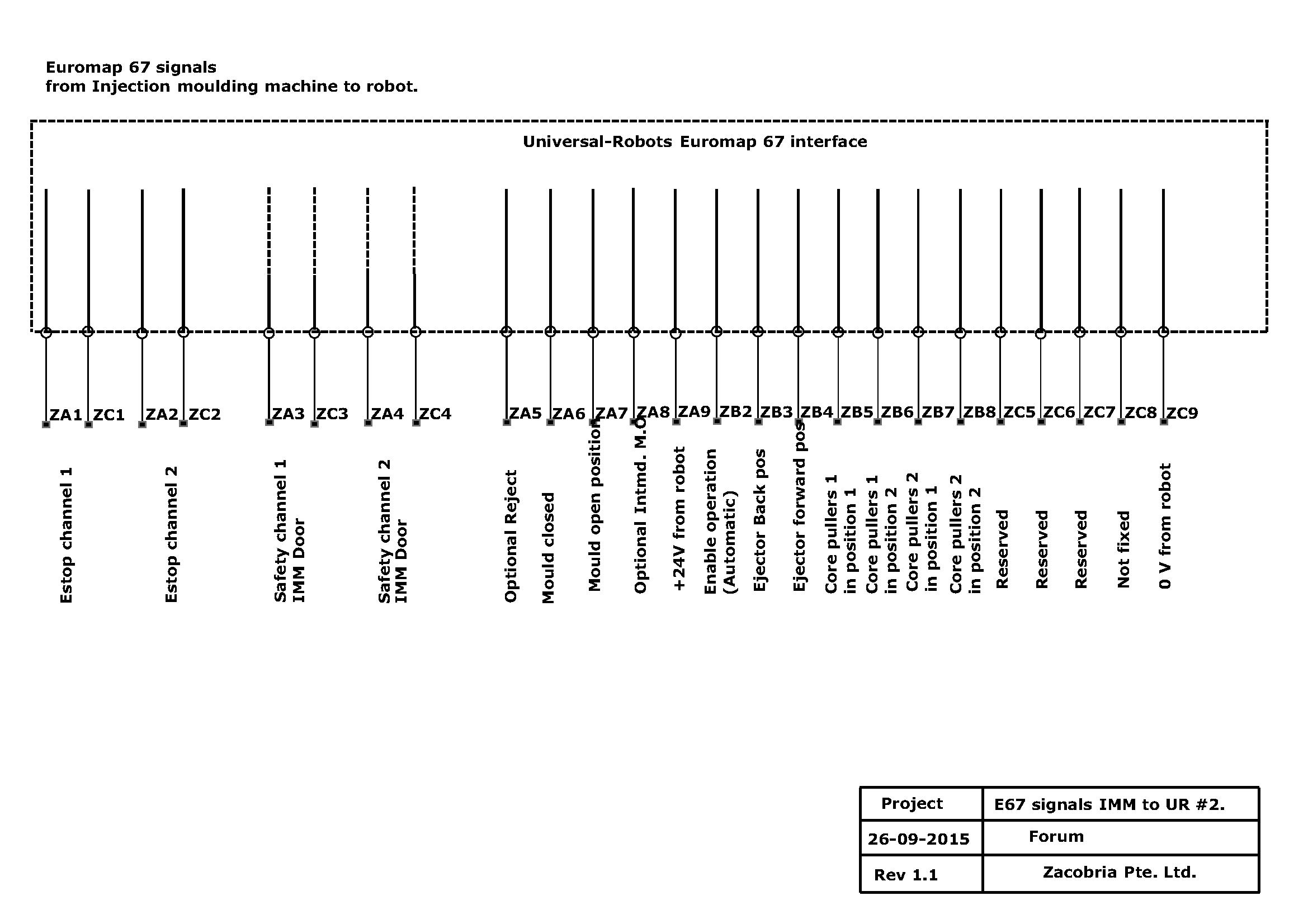
The exchange of electrical signals between. Connection of an external handling device eg. E67 pinout j3 tips electrical wiring euromap 12 version 17 euromap 12 of page 5 10 22 switch contact specification the current of the signals must not exceed 200 ma unless otherwise noted. Euromap 67 12 signal interface. Hyrobotics corp 5319 brown ave saint louis mo 63120. Wiring is done by euromap 67 to euromap 12 just plug and operate robot.
In addition recommendations are given for signal voltage and current levels. A current of at least 6 ma must be maintained during signalling the maximum current is 6a 222 logical signals. Session request file commands and responsesthis euromap recommendation defines theconnection between the injection. Euromap 12 extra pin 25 wire electric cable ready to use. A controlled robot via a standard signal interface in accordance to euromap 12 standard 32 pin. This is intended to provide interchangeability.
Seems pretty easy to forgo spending 100 on a reverse lockout. Wiring is done by euromap 67 to euromap 12 just plug and operate robot. With an e67 old e12 interface you can be extremely versatile in your use of handling equipment function description. Euromap 67 version 10 euromap 67 page 4 of 10 22 contact specification 221 emergency stop safety devices mould area free the voltages of the signals must not exceed 50 v dc or 250 v ac. Euromap 12 version 17 euromap 12 of page 5 10 22 switch contact specification the current of the signals must not exceed 200 ma unless otherwise noted. Euromap 67 for robot.
A current of at least 10 ma must be aintained during signalling. Euromap 67 version 111 euromap 67 page 3 of 9 1 scope and application this euromap recommendation defines the connection between the injection moulding machine and the handling device robot. The voltages of the signals must not exceed 50 v dc or 250 v ac.
Gallery of Euromap 67 To 12 Wiring Diagram