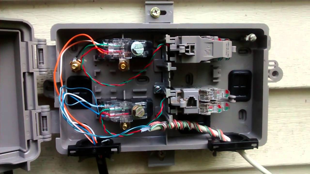
A diagram displaying a basic demarc extension. In the interface box there is an rj45 jack with a short pigtail plugged into it.
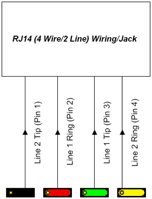
Telephone Rj11 Wiring Reference Free Knowledge Base The
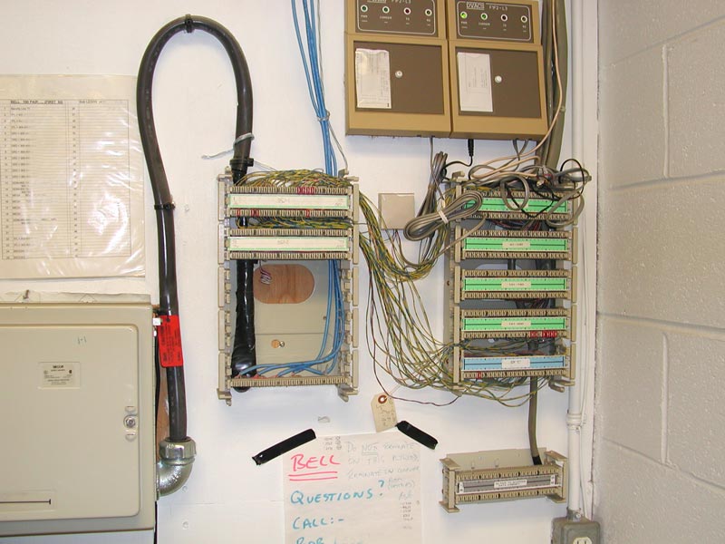
Demarc box wiring diagram. This may include in segment equipment media converters and patch cords as required to complete the circuits. Older telephone wiring was a basic cat 3 4 conductor or 2 pairs with red green black yellow. Pictures of the demarc and inside house fuse panel bell box connection. I am extending a demarc for a t1 from an interface box installed by att to a rj48x jack in the equipment room. Inside wiring extending from the mpoe to your location when a telecom service is provided to a commercial building it is typically delivered to the minimum point of entry mpoetelco room. The customer side of the box typically contains the wiring posts for each of the houses internal phone lines and a customer test jack which is simply a normal wall style jack for a normal phone cord.
How to do basic telephone wiring and line testing and repairs. Every run of wire should start at the demarcation point or if phone service has never been installed at your location at a point close to the main electrical panel. Demarc extensions like demarcs themselves have many names attributed to them. Newer homes can have anything from cat 3 3 pair on up to cat 5e with 4 pairs with the insulation colors being a combination of solid and solid with white for each wiring pair. Hook the new ground wire anywhere on that main ground wire. Demarc box wiring diagram ac maker design im ice car about.
The idea here is that if a problem occurs the customer can open the simplified side of the box and try the line with a standard phone. Has anyone found a good schematic for this with all the parts rj this. Of its entrance point if the pipe is metal. To read a wiring diagram first you have to find out what fundamental elements are included in a wiring diagram and which pictorial symbols are utilized to represent them. Leave approximately 1 metre 3 feet of wire hanging at the demarcation point. Cabling from the demarc must extend to a wiring closet or data distribution system to integrate with your network.
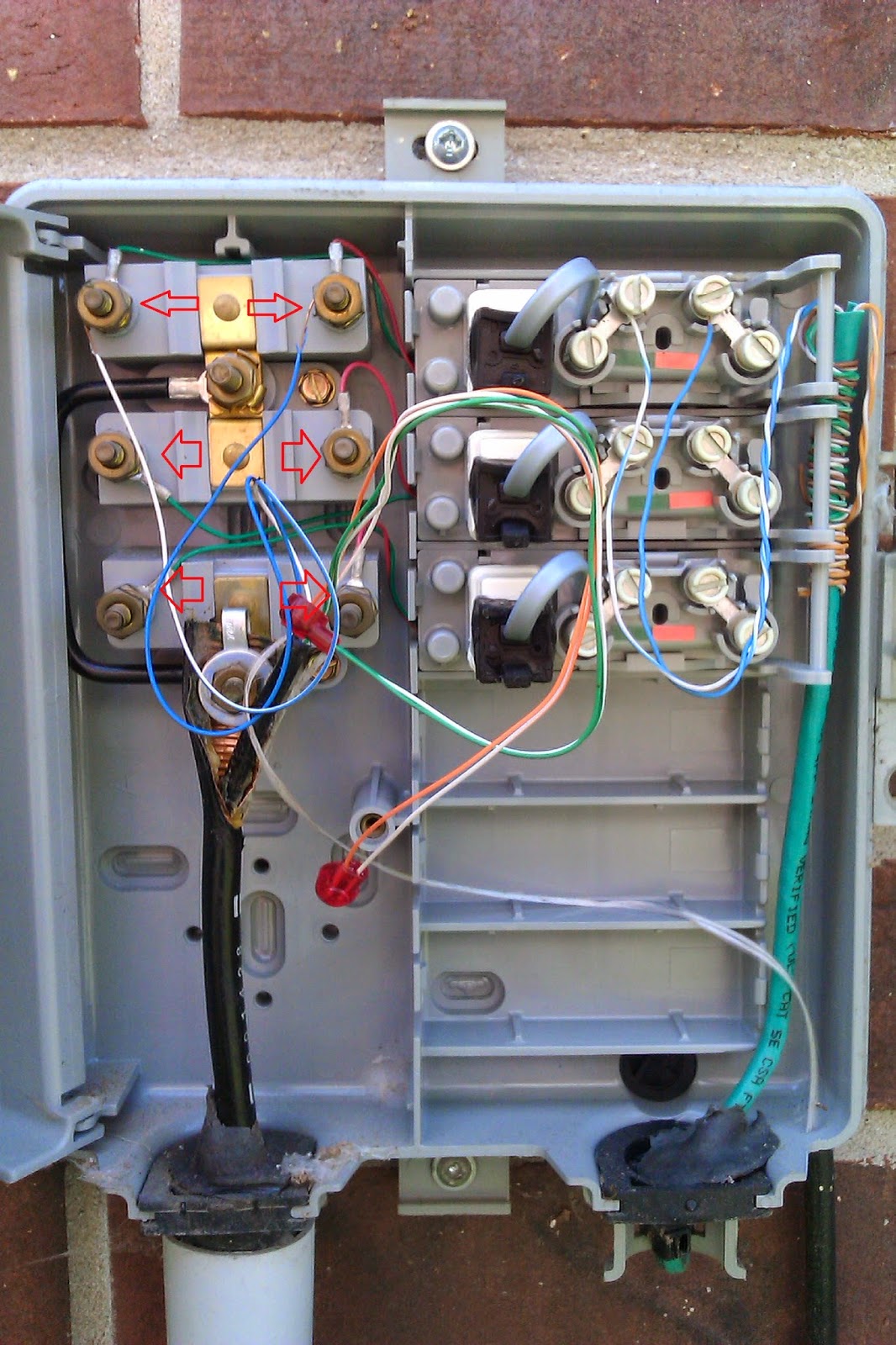
We show connecting a 10 gauge wire from the ground screw in the box to the main ground wire of the electrical service panel. A demarcation point extension or demarc extension is the transmission path originating from the interface of the access providers side of a demarcation point within a premises and ending at the termination point prior to the interface of the edge customer premises equipment cpe. The exact details will depend on the demarcs location and your buildings layout. How to read wiring diagram. The wire pair colors are blue orange green and brown. The common elements in the wiring diagram are ground power wire and connection output devices switches resistors logic gate lights etc.
This demarcation point or demarc is generally the point at which you become responsible for the on premise cabling and wiring. I you would be connecting the wires with the same color as what you have at. You can also attach the ground to your main water supply pipe within 5 ft. Ct1 cr1 ct and cr. A customer distribution device or connector block should be installed at this location. The terminals on the interface box are labeled.
Gallery of Demarc Box Wiring Diagram