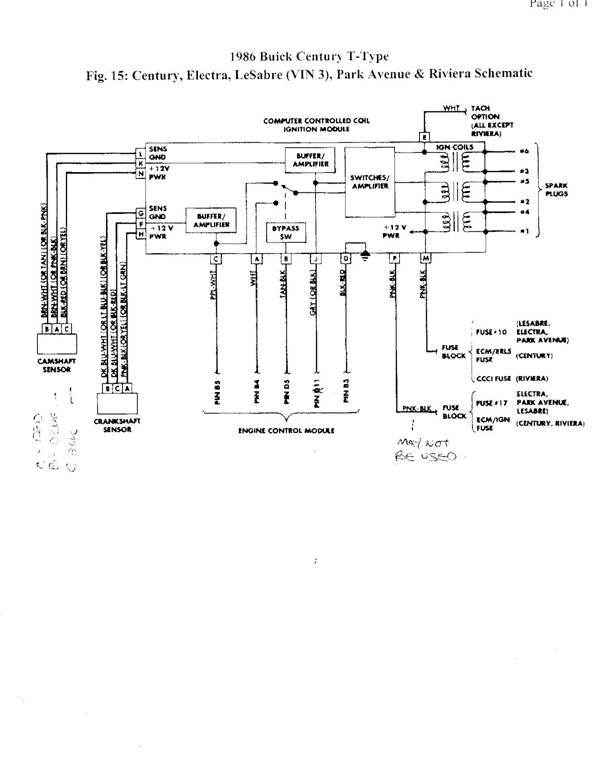
It shows the components of the circuit as simplified shapes and the skill and signal connections between the devices. January 30 2020 written by.

B884a Gm Tps Wiring Wiring Resources
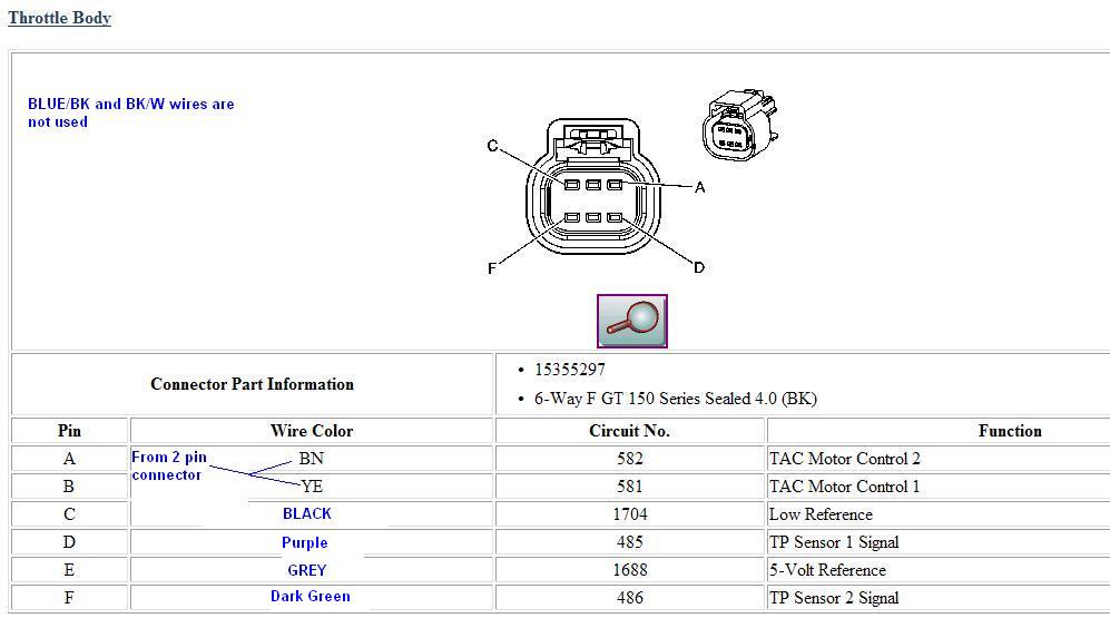
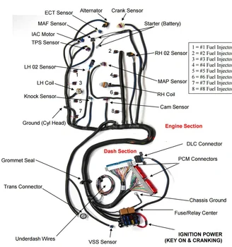
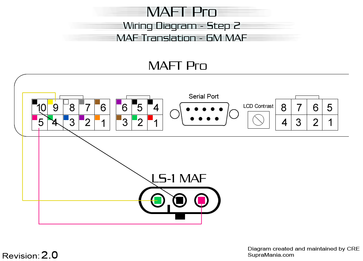
Gm tps wiring diagram. Everything you read about these systems indicate that they are the best thing to ever happen to automobiles. Tps kit below but do not assume that this pin out is valid for any other tps. How to wire up a 3800 pcm from a 1994 95 chg body car or u body van to run a 3800 series 2 l67l36 in your fiero. Otherwise the arrangement wont work as it ought to be. Throttle position sensor wiring diagram dodge throttle position sensor wiring diagram ford throttle position sensor wiring diagram gm throttle position sensor wiring diagram every electric structure is composed of various different components. Tps wiring differs between series 1 and series 2 engines make sure you are using the correct instructions for your engine type.
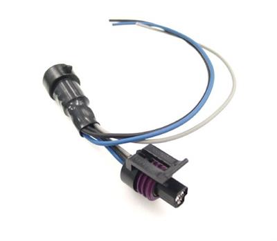
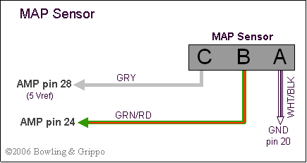
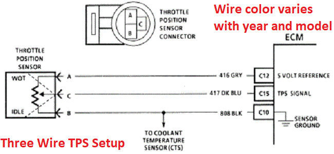
Gm tps wiring diagram wiring diagram is a simplified gratifying pictorial representation of an electrical circuit. Ignition system wiring diagram 2002 2005 42l chevrolet trailblazer february 06 2019 updated. Each part ought to be placed and linked to different parts in particular manner. Black is always ground grey is the 5 volt reference feed to the sensor and blue is the signal. The electronic throttle body. Fly by wire systems are being used in a lot of cars and pickups on the road today and one of the most common fly by wire systems in use is the one that graces most of the newer gm pickups.
Gm is consistent with the wiring colors for their tp sensors. Works with pcm service numbers.
Gallery of Gm Tps Wiring Diagram