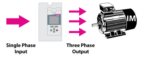
This free mounting position offers wide flexibility in system design and motor connection. For vlt 5122 5552 380 500 v vlt 5032.
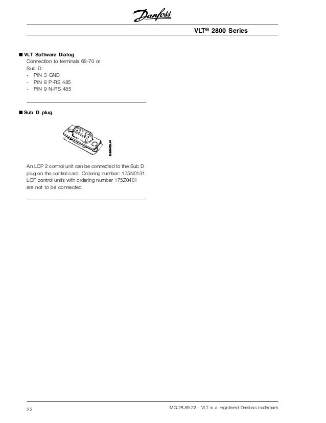
Lcp2 Control Panel Wiring Diagram
Danfoss vlt 2800 wiring diagram. Danfoss vlt 2800 wiring diagram line and components ac line transformer wires fuses and the danfoss vlt controls both the amplitude and the. It shows the components of the circuit as simplified shapes and the talent and signal associates in the midst of the devices. Danfoss offers an extensive portfolio of low voltage drives and will help you select the optimal replacement drive for your application. Startstop of motor is to be done with the switch. Vlt 2800 has a pulse pattern in which it is possible to set the switching frequency from 30 100140 khz. Must be derated in accordance electronics of the frequency converter.
Mg51a802 vlt is a registered danfoss trademark 5. Danfoss vlt 2800 design manual 162 pages. Control of mechanical brake 71 access to control terminals 71 electrical installation control cables 72. Diagrams below figure a and b. 7111 fixed variable speed pump wiring diagram 127 7112 lead pump alternation wiring diagram 127 7113 cascade controller wiring diagram 128 7114 startstop conditions 129 8 installation and set up 130 81 installation and set up 130. Mg28a722 vlt is a registered danfoss trademark 7.
Also see for danfoss vlt 2800. With the diagram below. This design guide can be used for all vlt series frequency converters with contact danfoss drives for further infor 6 wires out of motor delta con. All vlt 2800 units can be installed side by side since they do not require side cooling. Mg27a202 vlt is a registered danfoss trademark 1. Vlt 2800 nema 1 terminal covering mi28exyy vlt 2800 devicenet cable mi28fxyy vlt 2800 blue star condensing unit mi28gxyy vlt 2880 2882 spare part instruction mi28hxyy wobble function mi28jxyy vlt 2800 lcp remote mounting kit mi56axyy user instruction for lop mi90exyy brake resistor mi90fxyy profibus dp manual mg90ax.
Setup will guide you through emc correct installation of the frequency converter by connecting power motor and control wiring fig. Mg27e202 vlt is a. Vlt 2800 frequency converters allow side by side in stallation. Because of the need for cooling there must. Danfoss vlt 2800 wiring diagram wiring diagram is a simplified suitable pictorial representation of an electrical circuit. Mg14i102 vlt is a registered danfoss trademark 1.
The vlt 2800 mounts in virtually any position. Danfoss vlt 2800 manual 63 pages. 345 terminal tightening torques 26 346 input line connection 26 347 motor wiring 26 348 grounding earthing 27 349 control wiring 27 3410 serial communication bus connection 28 3411 programming 28 4 start up 29 411 inspection before start up 30. The vlt 2800 has reached the limited phase of its lifecycle and is no longer in active production. Danfoss vlt.
Gallery of Danfoss Vlt 2800 Wiring Diagram