Qs system qse ci dmx control interfaces 369372 rev. Qs system qse ci dmx control interfaces 369372 rev.
Qs Dmx Control Interface Mr Resistor
Lutron qse ci dmx wiring diagram. 7 wire occ sensor with photocell. Another option is to power the qse ci dmx from a qs link power supply qsps p1 1 50. Dmx 512 link wiring qse ci dmx control interface installation and operation instructions 3 connect the dmx link terminals on the qse ci dmx interface to input terminals on dmx512 controlled equipment. Easily monitor control and optimize a lutron control system from any tablet pc or smartphone. 500r 1000r or 2000r models note. A 7 121510 powering the qse ci dmx power for one qse ci dmx counts as two devices toward the maximum of three devices per grafik eye qs control unit when powered off of pin 2 of the grafik eye qs.
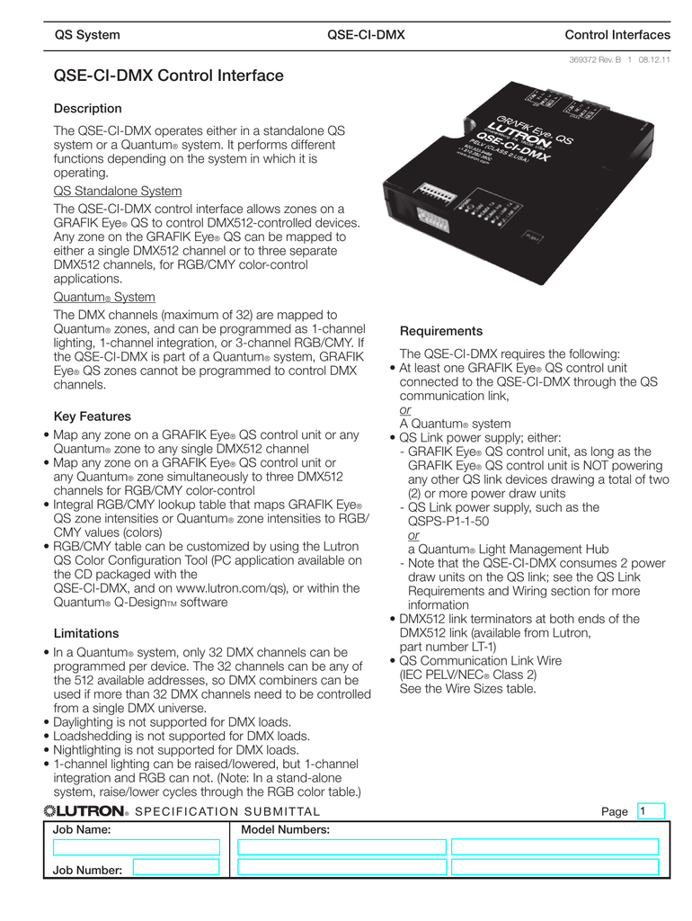
32 dmx channels per qse ci dmx control interface. Wiring diagram is not applicable to. Another option is to power the qse ci dmx from a qs link power supply qsps p1 1 50. Each qse ci nwk e control interface consumes 2 power draw units pdu on the qs link. The rgb led fixture will go to the color programmed for that scene and the stage light will go to the desired intensity. Lutron grafik eye qs control unit qse ci dmx selv pelv nec class 2 qs link wiring for system communication dmx output.
Lutrons new facility management tool empowers you to manage your building from anywhere. Follow all local and national electrical codes when installing 2 connectivity please refer to the wiring diagrams below. The qs wired communications link is limited to 100 devices and 512 switch legs each dmx channel 1 switch leg. The maximum wiring length for the qs link is 2000 ft 610 m. Link must be 1000 feet 305 m or less. Lut dmx dmx output yes yes yes qse ci dmx dmx output yes qse io contact closure output yes yes grx io contact closure output yes omx io contact closure output yes yes hw cco 8 contact closure output yes omx ci rs232 rs232ethernet output yes homeworks p5 processor rs232ethernet output yes.
The qse ci dmx converts the zone intensities for that scene into dmx512 channel settings. Each feature is designed around what is most important to you how well your building is working. Each terminal accepts up to two 18 awg 10 mm2 wires. The qse ci dmx consumes 2 power draw units on the qs link. Each qse ci nwk e control interface counts as 1 device and 0 zones. Selv pelv necr class 2 wiring with line voltagemains wiring.
B 7 081211 powering the qse ci dmx power for one qse ci dmx counts as two devices toward the maximum of three devices per grafik eye qs control unit when powered off of pin 2 of the grafik eye qs. Each terminal on the qse ci dmx accepts two 18 awg 10 mm2 wires.
Gallery of Lutron Qse Ci Dmx Wiring Diagram