Its likely though youve already read the wikipedia page about series and parallel circuits here maybe a few other google search results on the subject and are still unclear or wanting more specific information as it pertains to leds. It reveals the parts of the circuit as simplified forms and also the power as well as signal links in between the tools.

Autolumination Explanation Of Difference Between 7443 3157
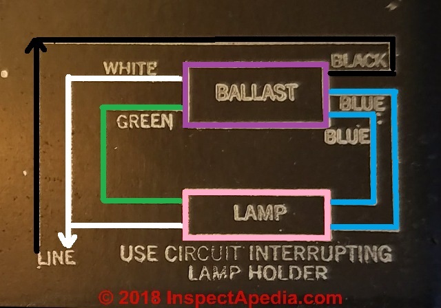
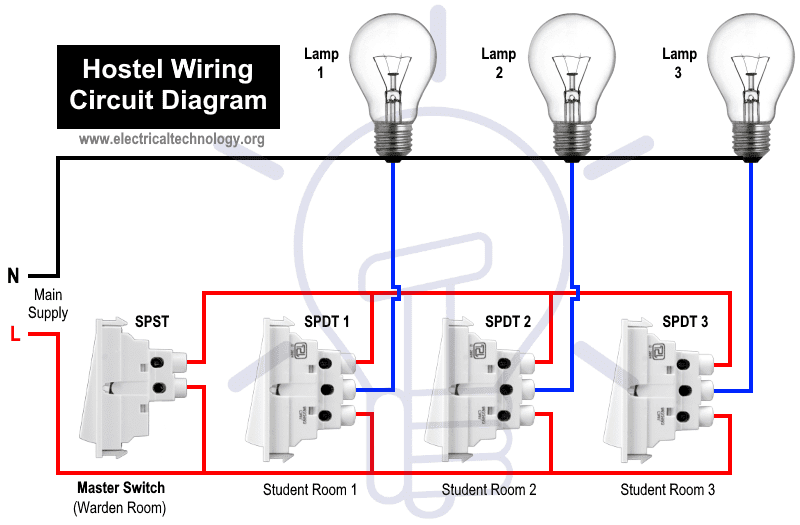
Bulb wiring diagram. How to install a single tube light with electromagnetic ballast from the junction box the neutral wire is not taken out to the switch board rather it is taken out from the junction box and carried out to the port 2 of the tube light as per figure above. The hot and neutral terminals on each fixture are spliced with a pigtail to the circuit wires which then continue on to the next light. Assortment of t8 led tube light wiring diagram. Wire a light switch video tutorial. The main bulb threads into a standard socket with an integrated switch and the three peripheral bulbs are wired to a single switch usually located near the central socket. 3 bulb ballast wiring diagram what is a wiring diagram.
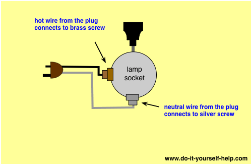
You need to connect your neutral wire to light socket and hot wire to the switch and from the switch you connect the wire to light bulb socket other free terminal and ground wire to the one way switch earthling point as i shown in the below diagram. This diagram illustrates wiring for one switch to control 2 or more lights. Wiring diagram ballast e bulb fluorescent light yellow wire. Different electrical symbols are used to make the wiring diagram below. Hopefully those looking for practical information on electrical circuits and wiring led components found this guide first. Collection of 4 bulb ballast wiring diagram.
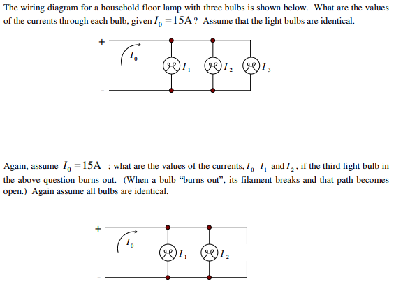
4 bulb ballast wiring diagram sample ge ballast wiring diagram bestharleylinksfo. Electricians usually refer to a light bulb as a lamp. Parallel ballasts can only be wired in parallel according to the diagram on the ballast. A wiring diagram is a simplified standard pictorial representation of an electrical circuit. This is a wiring diagram for a vintage floor lamp with 4 bulbs one main bulb and 3 peripheral and usually smaller bulbs. It shows how a electrical wires are interconnected and will also show where fixtures and components could be attached to the system.
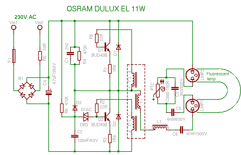
A wiring diagram is a streamlined conventional photographic representation of an electric circuit. Light bulb manufacturers use the term lamp when referring to fluorescent lights. It shows the parts of the circuit as streamlined forms and also the power and signal connections between the gadgets. 4 lamp t12 ballast 4 lamp emergency ballast wiring diagram wiring. A wiring diagram is a straightforward visual representation of the physical connections and physical layout of the electrical system or circuit. The source is at sw1 and 2 wire cable runs from there to the fixtures.
2 lamp t8 ballast wiring diagram 4 bulb ballast wiring diagram. Wiring of a light switch is very simple and easy connection. Changing the wiring on a fluorescent light fixture from series to parallel involves changing the.
Gallery of Bulb Wiring Diagram