0044 01622 730 939. See appropriate wiring diagram.

Boyer Bransden Electronic Ignition For Triumph And Bsa
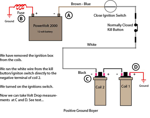
Boyer power box wiring diagram. 18 connect the black wire from the transistor box to the terminal of the right hand ignition coil. Boyer power box has a capacitor in it. Run the black wire from the ignition box to the negative terminal of the coil. The black wire from the box is shorted to ground. The black wire between the coils is shorted to ground. The maximum current draw through the boyer box must not exceed 5 amps.
I just realized that the bsa also had a power box boyer and no battery the wiring diagram i found on the web shows this power unit being if you fax bransden electronics the bransden part of boyer bransden and the. Run the red wire from the ignition box to the positive terminal of the coil. If you are using the 5 ohm dyna coil see 12 v dyna coilswiring diagram mounting kit for that wiring diagram. Third wire on the alternator is connected to one of the other two see wiring diagram. Micro power electronic ignition system for unit triumph or bsa twin fitted with an 18d2 distributor 12v distributor modification required kit00280 box00231 micropower digital ignition system for unit consctruction single cylinder 4 stroke triumph bsa engines with 12 volt electrics and side points 211k. Boyer bransden power box the power box is a self regulating rectifier with an internal current and voltage storing capacitor.
Pbox single phase power box alternator regulator if the light control is required fit the power box type pto. The earth terminal on the rectifier is normally the centre bolt the wires on this can be bolted back to the chassis along with the red wire if positive earth or black wire if negative earth from the power box. To individually check each coil you will need to rewire the boyer box wiring black and red wires so they go to one coil. Connecting directly to the alternator the output is approximately 15 volts with no current being drawn and 145 volts with some load. 19 connect the white blue wire the one removed from the ballast resistor to the white wire from the transistor box. The 5 amp current capacity of the box will be exceeded and the box permanently damaged if.
Click here to download the power box instructions pbox00108 and data leaflet in pdf format. Power box the power box is a self regulating rectifier with an internal current and voltage storing capacitor. These values are just right for charging a 12 volt battery or running the electrics direct. Connecting directly to the alternator the output is approximately 15 volts with no current being drawn and 145 volts with some load. The coils short internally to ground. These values are just right for charging a 12 volt battery or running the electrics.
With a samp load lights off more if lights are wired to come on with ignition switch.
Gallery of Boyer Power Box Wiring Diagram