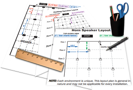
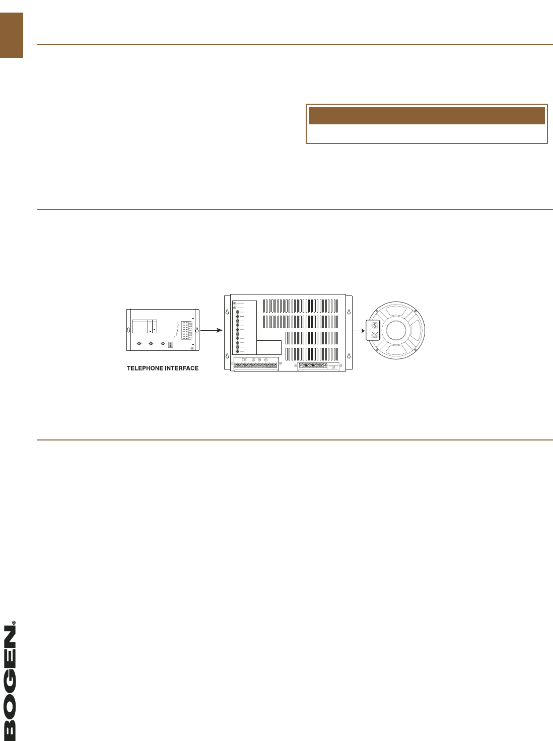
Paging system the most important thing to remember about surveying designing and quoting a telephone paging system is that there is no mystery or magic involved. Connect the bogen amplifier to the ac power outlet 120v ac 60hz.

Bogen Catalog Sotel Systems
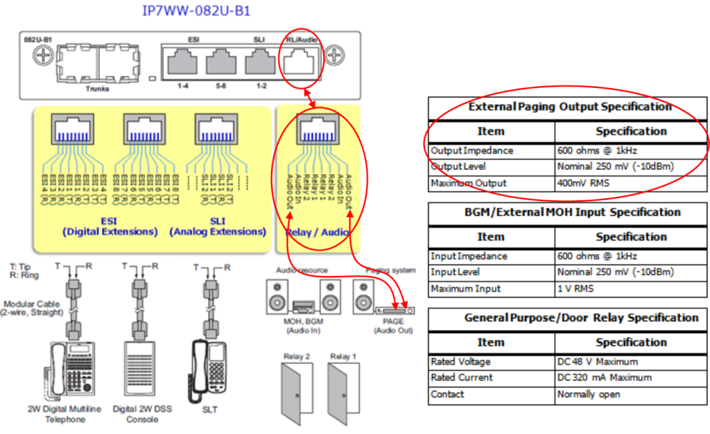
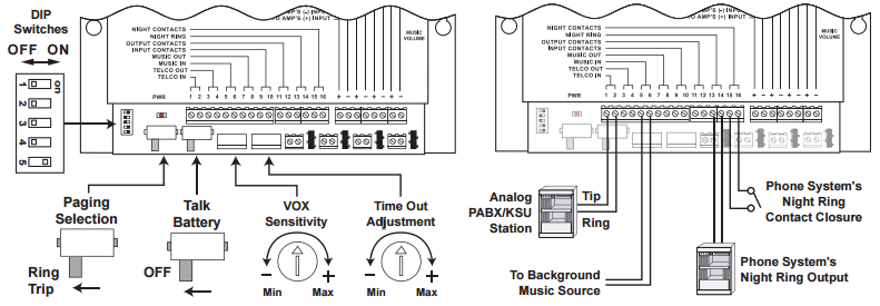
Bogen paging system wiring diagram. It shows the components of the circuit as simplified forms and also the power and also signal links in between the tools. The 70 volt system delivers 100 of its full rated power and the 24 volt system encounters power loss due to dc line loss. The 24 volt system on a two pair cable. Bogen paging system wiring diagram download collection of bogen paging system wiring diagram. Series parallel speaker wiring wire loss chart notwithstanding bogens efforts to ensure the accuracy of these drawings bogen makes no representation or warranty express or implied as to the accuracy or reliability of the drawings or any statement depiction or implication set forth therein or arising therefrom as to the product to which. A wiring diagram is a simplified conventional pictorial representation of an electric circuit.
System covers an area is to test it. A wiring diagram is a streamlined conventional photographic depiction of an electrical circuit. Never install a paging system and leave the site without testing it. Collection of bogen paging system wiring diagram download variety of bogen paging system wiring diagram. The successful system design is one that combines good old fashioned common sense with a few rules of thumb and commonly practiced installation guidelines. Volume controls and amplifiers in each speaker.
Set the volume on your bogen amplifier to a 12 turn. Access the paging from the telephone system and listen on the handset for the confirmation tone double beep. If youre working in medium to large projects the 70 volt system is economical and the 24 volt system is not. Some paging equipment such as bogens pcm2000 uti1 and uti312 paging interfaces include a test tone that is sent to all speakers in the system so installers can check the. Sound adjust ments or additional speakers may be needed. It shows the parts of the circuit as streamlined forms and also the power and signal connections in between the devices.
One way all call to all speakers available. One way paging system block diagram figure 1 features 1 3 6 and 24 expandable with v 2925a in 24 zone increments for up to 96 zone page control units available. The 70 volt system operates on a one pair cable.
Gallery of Bogen Paging System Wiring Diagram