To learn more please visit. Atv31h075m2 variable speed drive atv31 075kw 240v 1 phase supply emc filter ip20.
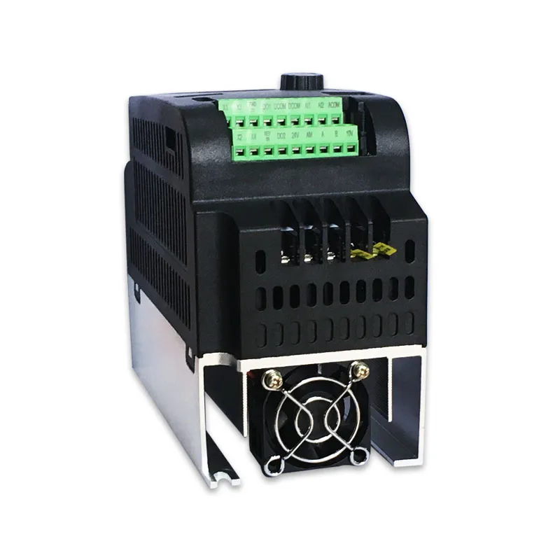
Us 80 04 42 Off 4kw 380v 3 Phase Inverter Input Vfd 3 Phase Output 4 0kw Frequency Converter Adjustable Speed 4000w 380v Inverter Inverters Amp
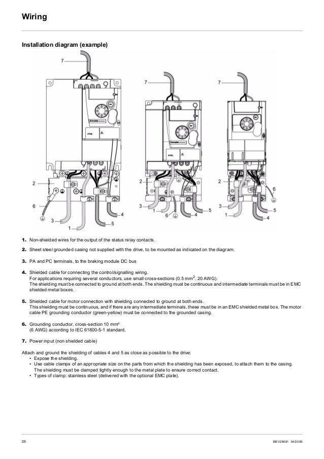
Atv12h075m2 wiring diagram. Altivar machine atv12 variable speed drive is designed for commercial equipment and small machines with 3 phase 240v for asynchronous motors which require emc standards up to c1 in residential areas. Wire the drive page 19 v connect the motor ensuring that its connections correspond to the voltage. Stop type external fault epl. It reveals the components of the circuit as simplified shapes and also the power and signal connections in between the tools. Wire the drive page 20 v connect the motor ensuring that its connections correspond to the voltage. External fault etf.
This represents a change in the nec code that. V connect the line supply after making sure that the power is off. Tutorial for configuring the altivar atv12 drive for local mode operation so you can control the drive with the startstop button and use the knob for speed control. For external fault management by logic input. Assortment of 12 volt relay wiring diagram. External fault assignment etf.
Configure the drive page 32 v apply input power to the drive but do not give a run command. V set the motor parameters in conf mode only. 650 588 9200 outside local area. Altivar 12 variable speed drives for 3 phase motors from 018 to 4 kw catalog 2010 courtesy of steven engineering inc 230 ryan way south san francisco ca 94080 6370 main office. V set the motor parameters in conf mode only. With dedicated functions and 3 macros applications startstop pid speed for simple environments.
Altivar 12 variable speed drives for commercial equipment from 018 to 4 kw. A wiring diagram is a simplified traditional pictorial depiction of an electrical circuit. Enhancements made to version v14 in comparison to v12 new menu. V connect the control part. V connect the control part. New wiring labels lo and lo instead of lo and clo see pages 18 and 19.
The neutral from the source is spliced through to the switch box using the white wire and in this diagram the white wire is capped with a wire nut. Configure the drive page 31 v apply input power to the drive but do not give a run command. V connect the line supply after making sure that the power is off. In this updated diagram 3 wire cable runs between the receptacle and switch and the red cable wire is used to carry the hot source to the switch.
Gallery of Atv12h075m2 Wiring Diagram