This panel is suitable for any generator set featuring a control module with amf automatic mains failure function. Ats wiring diagram for standby generator generac ats wiring diagram collection generac automatic transfer switch wiring diagram simple design between solargenerator download wiring diagram.
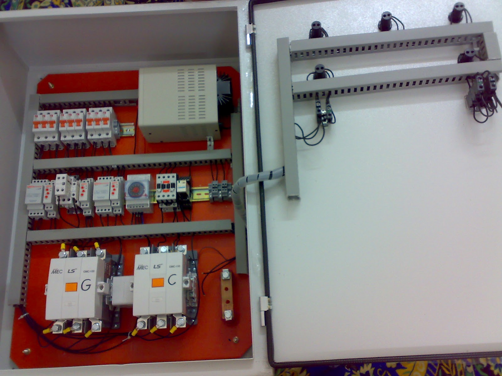
Ats Simply Portable Generator Transfer Switch Design And
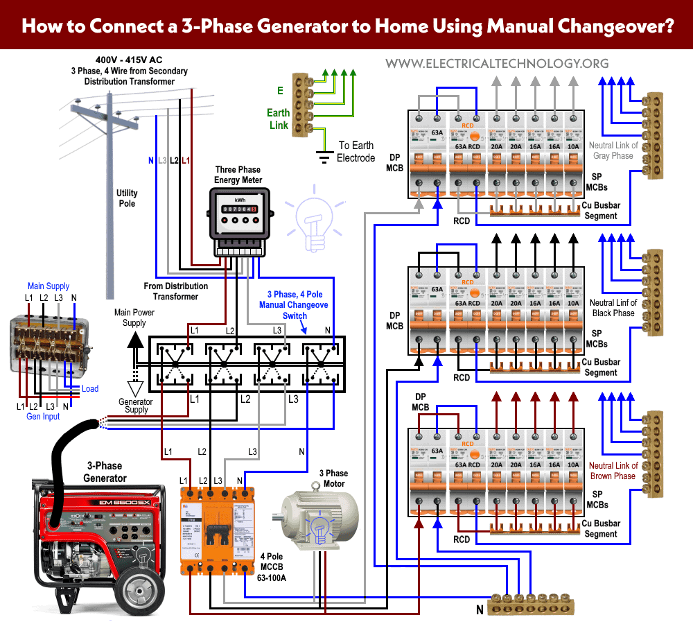
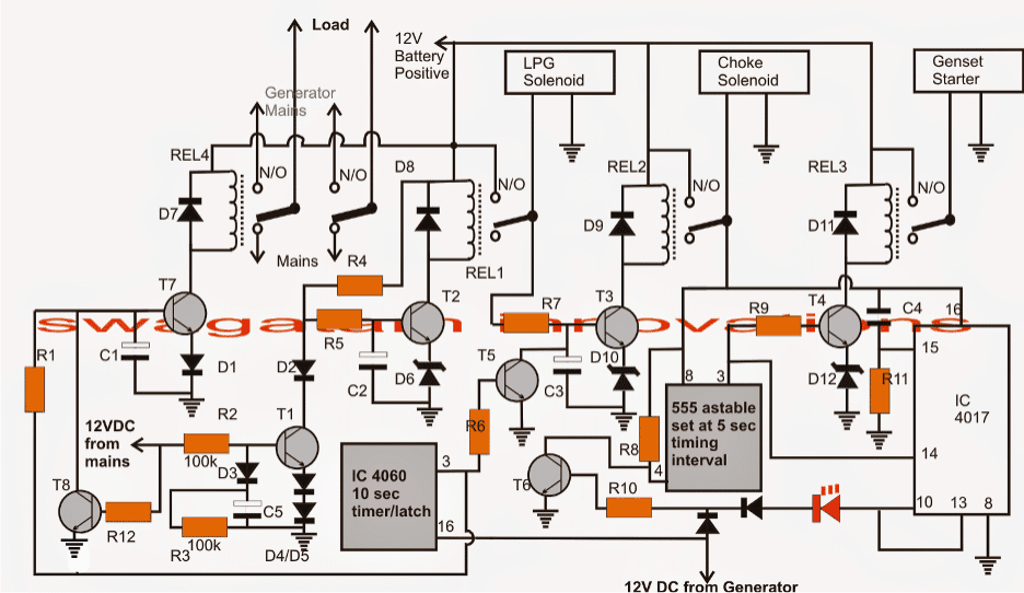
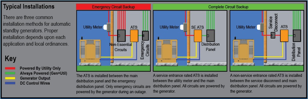
Ats panel for generator wiring diagram pdf. Verify the method of wiring with your transfer switch and generator before installation. Ats panel wiring diagram an automatic transfer switch wiring diagram an automatic transfer switch wiring diagram an generators 120 vac 50 amp automatic transfer switch from progressive dynamics generator transfer switch. Amf automatic mains failure panels ats automatic transfer switch panels app parallel applications. Ats when an electric utility outage occurs the ats will tell the backup generator to start. Figure 11 typical ats transfer mechanism utility closing coil generator closing coil utility lugs generator lugs e1 e2 load lugs t1 t2 this transfer switch is for use in optional standby systems only. Wiring the atsgts to the ups the atsgts should be wired to the ups as shown in figure 1 below.
Once the ats sees that the generator is ready to provide electric power the ats breaks the homes connection to the electric utility and connects the generator to the homes main electrical panel. Bottom cap for wiring inlet. 6 3 7 8 1 4 5 2 6. Variety of ats wiring diagram for standby generator. Single line diagram and connections functionality. Ats panel for generator wiring diagram pdf madreviewnet automatic transfer switch 200 amp single phase 240 vac service rated 8 16 circuit load center 28 pages switch generac power systems rxgw20sha3 many systems do not switch the neutral wire and tie the three neutral wires together.
The generator supply power to the homes electric. This transfer switch is suitable for use on a circuit capable of 10000 rms symmetrical amperes 240 vac maximum.
Gallery of Ats Panel For Generator Wiring Diagram Pdf