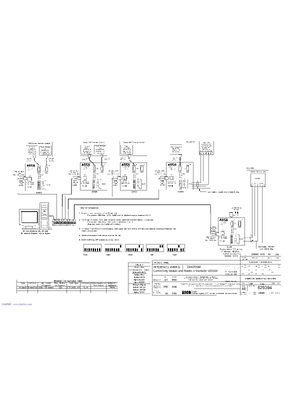
Wiring diagrams use the wiring diagram cross reference chart to determine the wiring diagram version number for a given model number and spec number. 300592901 panel mounted 300592902 panel with enclosure network types the universal annunciator can communicate using.

Push Buttons Switches Annunciators Bells Part 4
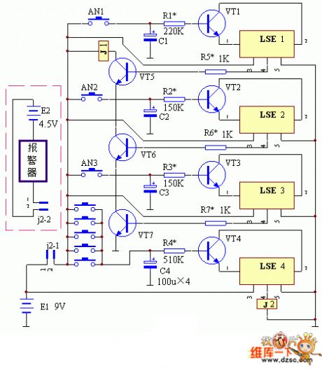
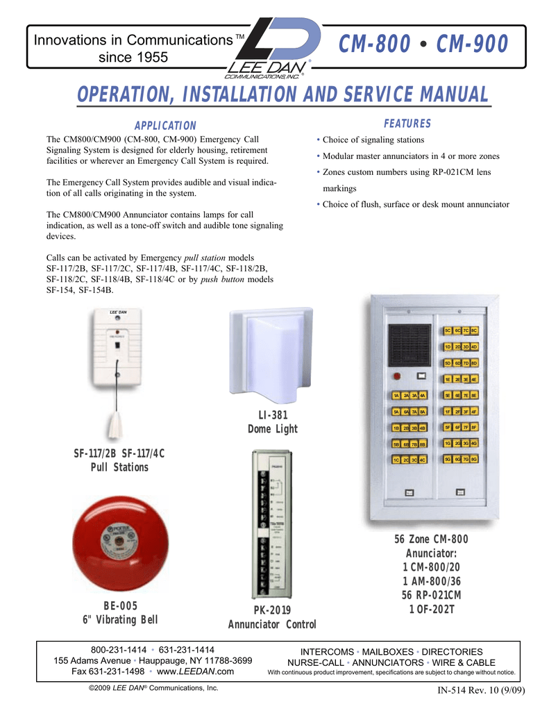
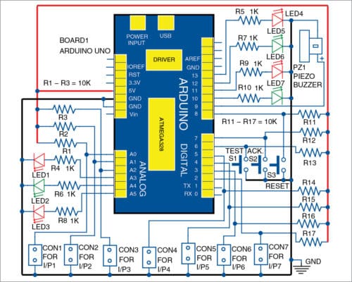
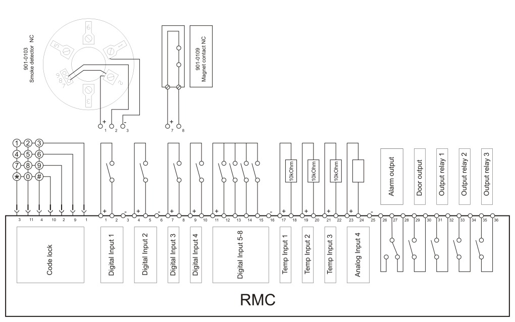
Annunciator wiring diagram. Wiring diagram for d4120 to apa151. Annunciator digital output selection. Annunciator screw compressor loading. 3 installing the 4603 9101 lcd annunciator figure 3. Annunciator digital out test screen. Two versions of the universal annunciator are avail able.
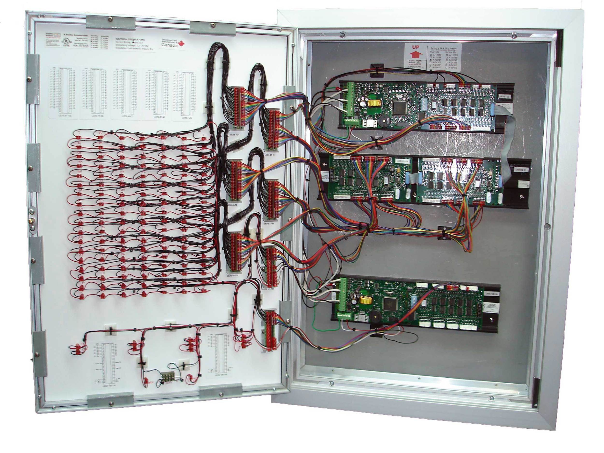
Annunciator rod load monitoring. The system sensor apa151 annunciator with piezo alert is an audible signal appliance for fire alarm service. Power and rui communicating wiring to tb1 and tb2 3. Call points sounders bells relay module repeater annunciator fire control panel and other related and optional security devices designed for fire alarm control system. Then find that version number the controller type and the alternator type on the wiring diagrams reference chart to determine the wiring diagram numbers for your unit. Wiring installation diagrams.
Like a cpu central processing unit in a computer system the fire alarm control panel is the brain of fire alarm. This annunciator can be used to replace legacy an nunciators 3004510 ann negative signal and 3004511 anp positive signal. Annunciator no flow status. Using switch sw2 see figure 4 set the annunciators address and baud rate in accordance. 10 9 19 20 1 12 15 3 2 1 apa151451 d4120 green led power field installed. It is intended for use in system sensor 4 wire.
Wiring diagram for d4120dh100acdc to apa151. Annunciator purge blowdown alarm setup.
Gallery of Annunciator Wiring Diagram