Xlr to 14 mono plug. It shows the components of the circuit as simplified shapes and the capacity and signal connections with the devices.
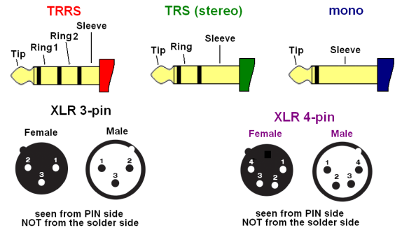
3 Pin Xlr Wiring Diagram Cable Wiring Etc
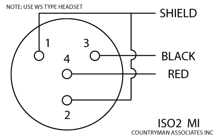
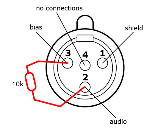
4 pin xlr wiring diagram. This wiring configuration gives you a balanced mono audio cable. Yellow and green are for left and right turns and braking. 3 pin xlr connectors are standard amongst line level and mic level audio applications. Pinout of professional audio entertainment devices 4 pin xlr connector and layout of 4 pin xlr female connector and 4 pin xlr male connector. It shows the elements of the circuit as simplified forms and the power and also signal connections between the tools. It shows the components of the circuit as simplified shapes and the capacity and signal links together with the devices.
4 pin xlr female connector. Pin 1 pin 1. Start by cutting the white wire and attaching it to the trailer frame. The most comon way to wire a 3 pin xlr to a 14 inch 65mm mono plug sometimes called a jack plug is to join the negative and shield together. Wiring diagram for a 4 pin relay wiring diagram is a simplified agreeable pictorial representation of an electrical circuit. The above diagram shows you the pin numbering for both male and female xlr connectors from the front and the rear view.
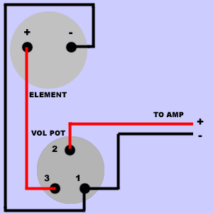
On the four pin amphenol pin 2 is a high impedance unbalanced output. Collection of xlr wiring diagram pdf. Speaker speaker cable 4 wire. Wiring of vintage shure mics. The rear view is the end you solder from here are the connections on each pin. A wiring diagram is a simplified standard photographic depiction of an electric circuit.
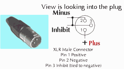
3 pin xlr wiring standard. Bias return 20 k ohm resistor to ground or equivalent active bias management circuit jumpered to pin 3 when used with most condenser microphones pin 4. This can be done by either soldering the shield and negative wires of the xlr to the sleeve of the plug. Installing the 4 pin trailer wires. You must check the trailer manual to see if the wiring is correct but normally the white wire is called the ground wire while the brown wire is used for tail lights. Pin 2 pin 2.
Xlr 4 pin wiring diagram may 05 2019 horbar. 4 pin mini xlr wiring diagram wiring diagram is a simplified usual pictorial representation of an electrical circuit. Speakon speaker cable 2 wire. 3 or 4 pin amphenol to xlr xlr pin 2 low impedance audio hot amphenol pin 4 white wire typically xlr pin 3 low impedance audio return amphenol pin 3 black wire typically note. An explanation and diagram showing how to wire an xlr cannon connector to a 14 inch mono phone jack connectorthe 14 connector on the other hand can have 2 or 3 wire terminals and is not standard.
Gallery of 4 Pin Xlr Wiring Diagram