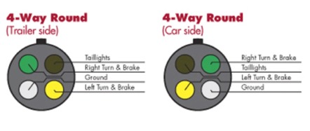
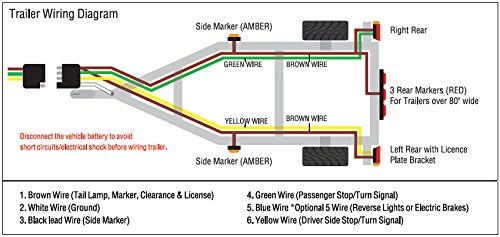
4 pin trailer wiring diagram this type of connector is normally found on utvs atvs and trailers that do not have their own braking system. 1 4 wire the first 4 pins white brown yellow green just like the 4 pin connector above.
4 Wire Trailer Wiring Harness Diagrams Diagrame 9
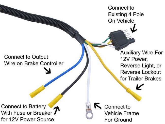
4 pin trailer wiring diagram. Various connectors are available from four to seven pins that allow for the transfer of power for the lighting as well as auxiliary functions such as an electric trailer brake controller backup lights or a 12v power supply for a winch or interior trailer lights. Note that this type of 4 pin connector is less common that 4 pin flat connector. Why does 4 pin trailer wiring have 5 wires. The red and blue wire can be used for brake control or auxiliary. Traditional trailer with brakes use a 5 pin connector. 4 way trailer connectors are typically used on small trailers such as boat snowmobile utility and other trailers that that do not use brakes.
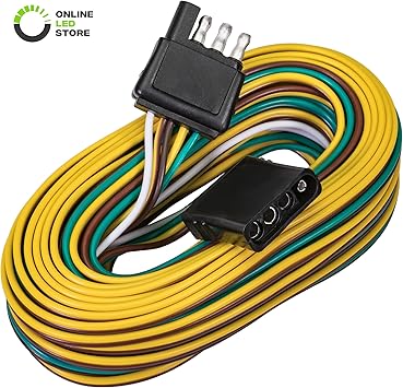
Buy a 4 pin wiring kit with wires at least twenty feet in length so its long enough for your trailer. 4 pin connectors are the standard used for most trailers. They also provide a wire for a ground connection. Use on a small motorcycle trailer snowmobile trailer or utility trailer. The most common wire thickness for a trailer is 16 gauge but i bought thicker wiring for added durability. 34 inch by 1 inch 6 way rectangle connectors right turn signal green left turn signal yellow taillight brown ground white.
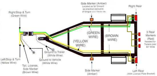
The four wires control the turn signals brake lights and taillights or running lights. Do 4 way connectors have a power wire. Depending on the size of your trailer and the number of lights you might want to check on the internet for the recommended gauge for your specific trailer. You must check the trailer manual to see if the wiring is correct but normally the white wire is called the ground wire while the brown wire is used for tail lights. Yellow and green are for left and right turns and braking. Wiring guide for installing lights on trailer with 5 wires.
Trailer lightingwiring kit for snowmobile trailer. Trailer wiring diagrams trailer wiring connectors. Connecting the wrong color wires will result in mismatched taillight functions and confusion on the road. The ground wire should be run from the frame of the. 4 pin trailer light wiring diagram. Replacement 4 pole trailer connector for utility trailer with 5 wire wishbone wiring setup.
Three wires are for the trailer while the last wire is the ground wire. Many trailers have three circuits. Blue electric brakes or hydraulic reverse disable see blue wire notes below in the trailer wiring diagram and connector application chart below use the first 5 pins and ignore the rest. As the name implies they use four wires to carry out the vital lighting functions. Can also be used as custom wiring on trailers with 3 lightwire systems. 4 pin trailer wiring diagram following the standard method for wiring a trailer connector is vital to the safety of your vehicle while towing.
The circuits are for left and right brake lights and running lights. Can trailer 4 way be ran to trailer with 8 wires for. Installing the 4 pin trailer wires. 4 way trailer connectors are. Start by cutting the white wire and attaching it to the trailer frame. As a rule you can find these connectors on the older trailers and older vehicles built in the us.
Gallery of 4 Pin Trailer Wiring Diagram