Wiring diagrams show components mounted in their general location with connecting wires. Numbers along the left side of diagram are line iden ti fi ca tion numbers.
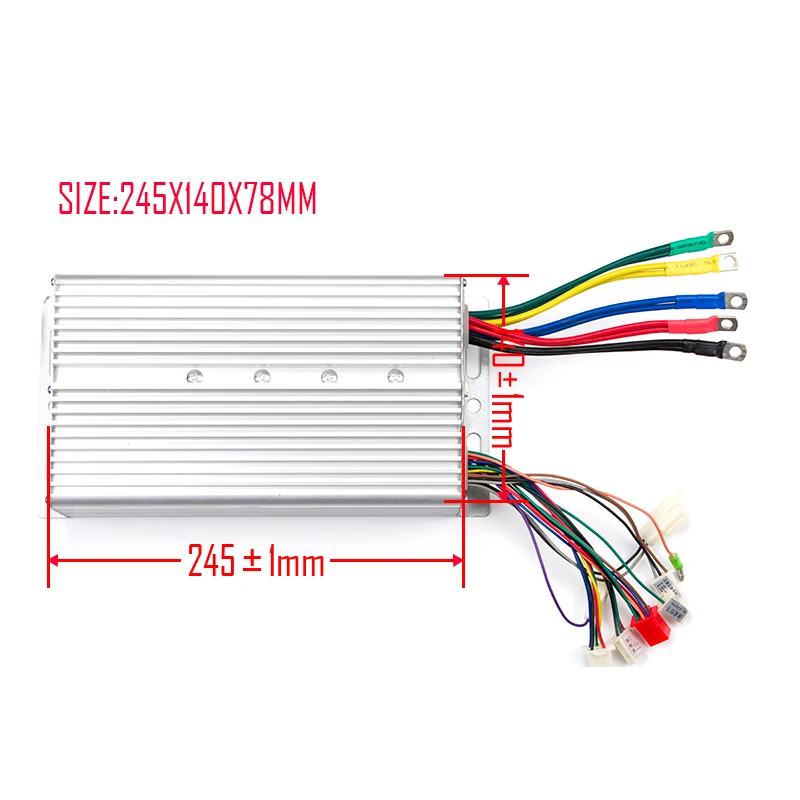
48 Volt Electric Scooter Speed Controllers
Yyk controller wiring diagram. A wiring diagram is a streamlined standard photographic depiction of an electric circuit. The numbers along the right side in di cate the line num ber location of relay contacts. These diagrams show the actual location of parts color of wires and how they are connected. It shows the components of the circuit as streamlined shapes and the power as well as signal links between the gadgets. Wiring diagram book a1 15 b1 b2 16 18 b3 a2 b1 b3 15 supply voltage 16 18 l m h 2 levels b2 l1 f u 1 460 v f u 2 l2 l3 gnd h1 h3 h2 h4 f u 3 x1a f u 4 f u 5 x2a r power on. This type of diagram is like taking a photograph of the parts and wires all connected up.
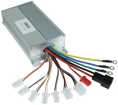
The controller sends power from the battery to the motor. Here we break down the basic. Wiring diagrams help technicians to see how the controls are wired to the system. 5 control wiring york international control wiring remote startstop pwm input ld03819 factory wired with optional transformer. It reveals the elements of the circuit as streamlined shapes as well as the power and signal links in between the gadgets. The new power panel switching system is designed to make it quick and easy for you to add and control 12v electronics on your kayak.
Wiring con nec tions. To help illustrate the differences between wiring diagrams and schematics a basic control circuit will first be explained as a schematic and then shown as a wiring diagram. If youre just wanting to add or connect led lights cleanup the wiring and control your existing electronics or simply add integrated switching to. A wiring diagram is a simplified traditional photographic representation of an electric circuit. Main control panel class 1 fi eld wiring terminal con. An un der lined con tact lo ca tion signi fi es a normally closed con tact.
Control wiring power from the unit at or below freezing temperatures can result in damage to the evaporator and unit as a result of the chilled liquid freezing. Variety of control 4 wiring diagram. Wiring diagrams yp rp5r power panel switching system 7999. A wiring diagram is used to represent how the circuit generally appears. Typical controller markings typical elementary diagram table 4 control and power connections for across the line starters 600 v or less from nema standard ics 2 321a60. Single door controlled egress wiring diagram 01 single door digital entry wiring diagram 10 single door dk 26 with door prop alarm wiring diagram 15 single door dk1 11 xms dt 7 wiring diagram 20 single door dk 26 remote release wiring diagram 14 single door dk 26 unl 24 and dt 7 wiring diagram 18 single door dk 26 using the hard code to toggle lock off and on wiring diagram.
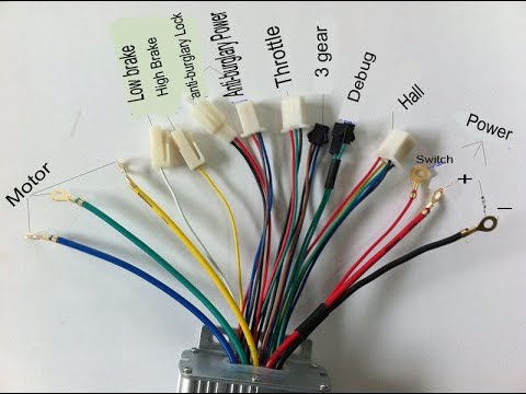
Variety of e bike controller wiring diagram. Many people can read and understand schematics known as label or line diagrams.
Gallery of Yyk Controller Wiring Diagram