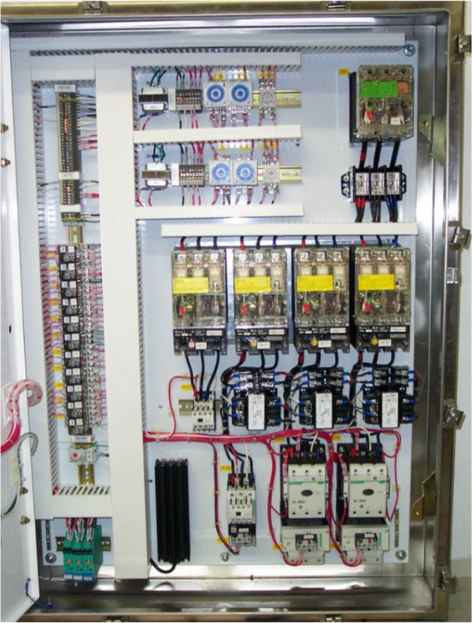
Assortment of pump control panel wiring diagram schematic. Pasang rangkaian kontrol dan rangkaian utama pompa sesuai gambar.
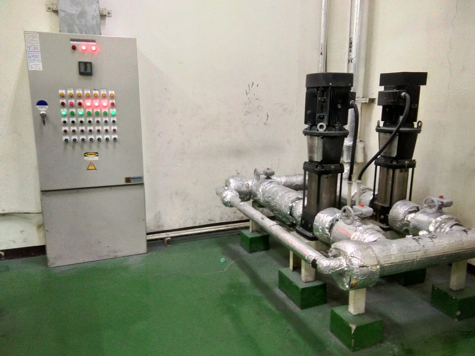
1 Phase Starter Panel
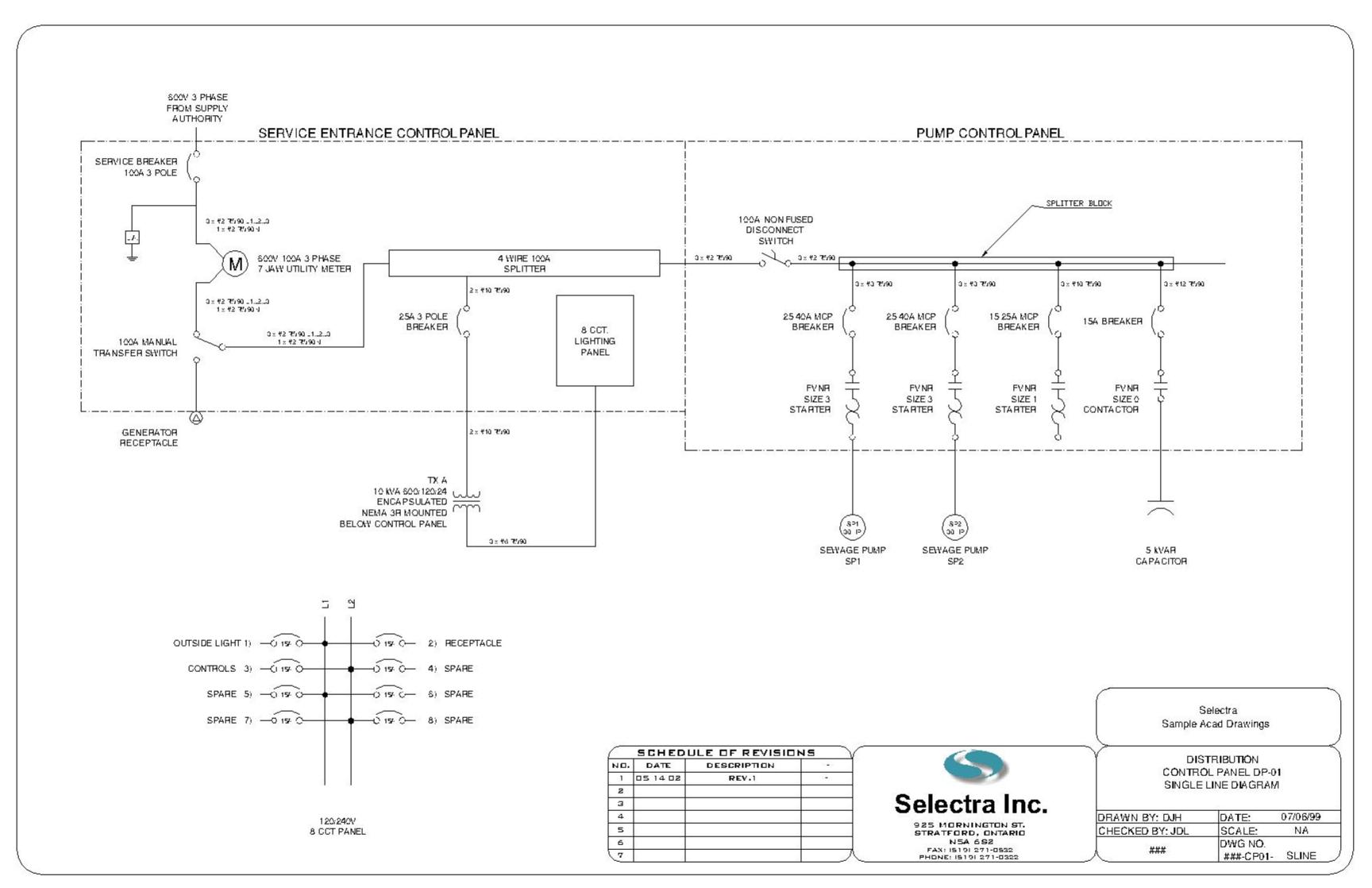
Wiring diagram panel pompa transfer. Replace the cover on the service panel box and make sure to fill in the circuit map on your switch box. Generator automatic transfer switch wiring diagram generac with. This should complete the installation of the transfer switch. The typical elements in a wiring diagram are ground power supply wire as well as connection output tools switches resistors reasoning gateway lights etc. Persiapkanlah terlebih dahulu perlatan dan bahan yang digunakan untuk merakit panel. They should join the circuit breaker through a knockout found at the bottom of the box.
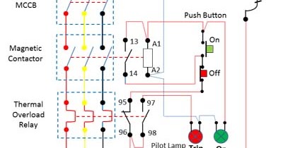
A wiring diagram is a simplified traditional photographic depiction of an electric circuit. Mengatur serapi mungkin kabel yang terhubung ke dalam rangkaian. To read a wiring diagram initially you have to recognize just what essential aspects are consisted of in a wiring diagram and also which photographic icons are used to represent them. Dewasa ini banyak teknologi teknologi baru yang terus berkembang dan hal tersebut seiring dengan perubahan zaman. Generac 200 amp transfer switch wiring diagram download wiring diagram controls for a transfer switch. Generac 200 amp transfer switch wiring diagram inspirational generac.
Langkah kerja cara merakit panel kontrol pompa. Wiring diagram book a1 15 b1 b2 16 18 b3 a2 b1 b3 15 supply voltage 16 18 l m h 2 levels b2 l1 f u 1 460 v f u 2 l2 l3 gnd h1 h3 h2 h4 f u 3 x1a f u 4 f u 5 x2a r. Attach the green ground wire from the transfer switch to an open port on the grounding bar in your main service panel. Use the transfer switchs wiring harness to connect the unit to the circuit breaker. It shows the parts of the circuit as simplified shapes as well as the power as well as signal links between the devices. Pasang komponen komponen ke dalam box panel sesuai pada gambar pengaturan.
Whole house transfer switch wiring diagram awesome 11 plus generator. Untuk kesempatan ke 5 pada sesi kontrol elektromagnetik ini akan kita bahas tentang perakitan panel kontrol motor pompa air 1 fasa dan 3 fasa. This video identifies the wires and voltage switch on the fr300 series ac fuel transfer pumps. Figure 4 wiring diagram of a manual transfer switch in the off position figure 5 wiring diagram of a manual transfer switch in the on position when utility power is functioning the wires from the circuit breaker in the main electrical distribution panel are connected to the generator sub panel. The wires should be drawn through 1 of 3 knockouts located on the underside of the switch.
Gallery of Wiring Diagram Panel Pompa Transfer