Electrical wiring layouts are made up of two points. Parts lists installation instructions.

Meyer Plow Power Wire Battery To Solenoid 24 Welding Cable
Western plow wiring diagram. Western snow plow solenoid wiring diagram. Attach spreader to mount frame with a 58 x 1 34 bolt and locknut through top hole in spreader angle on each. Dont see your plow. Diagnosis and repair of western snowplow electrical systems. October 20 2019 by larry a. See coupling lug height check near end of these instructions 2.
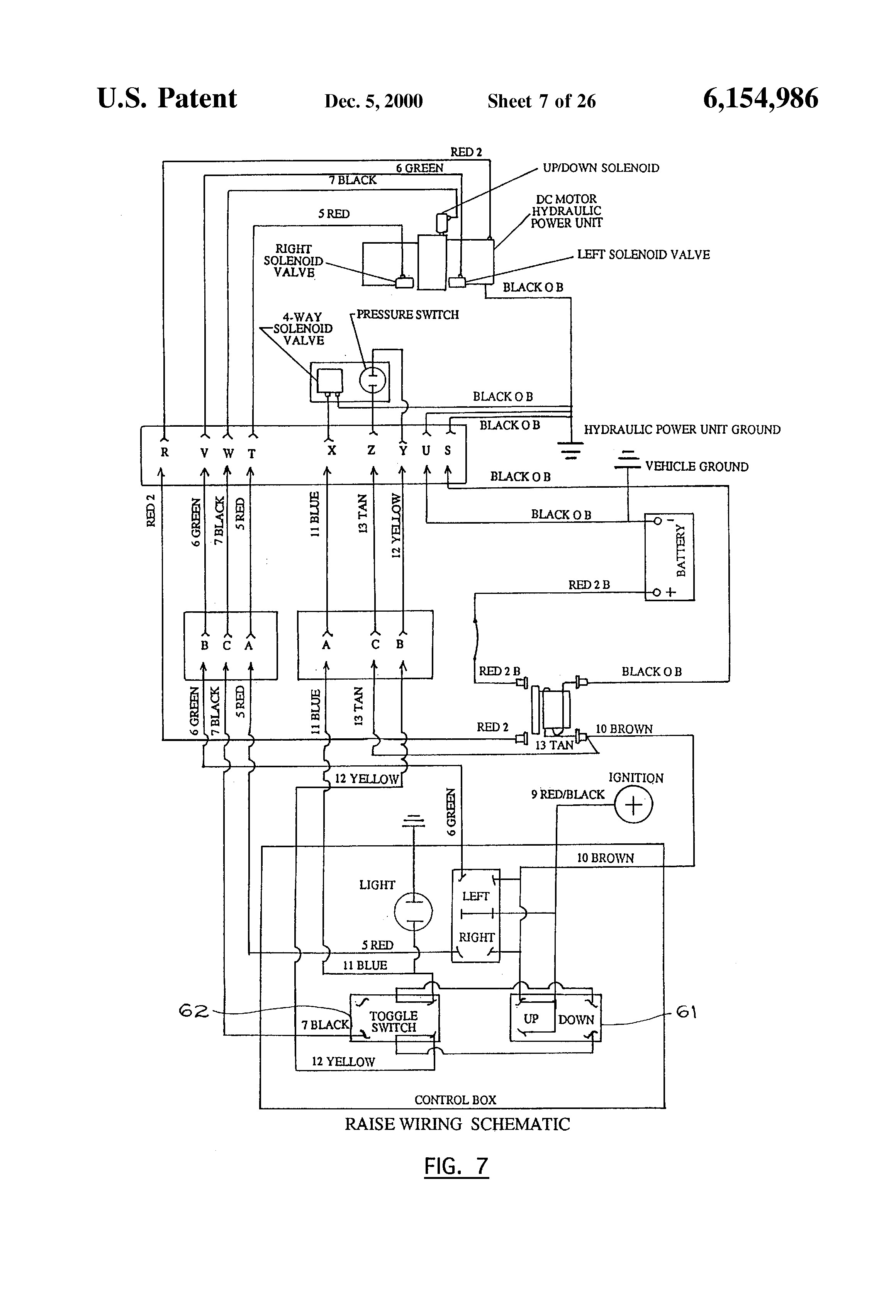
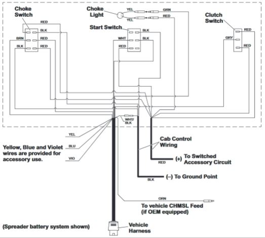
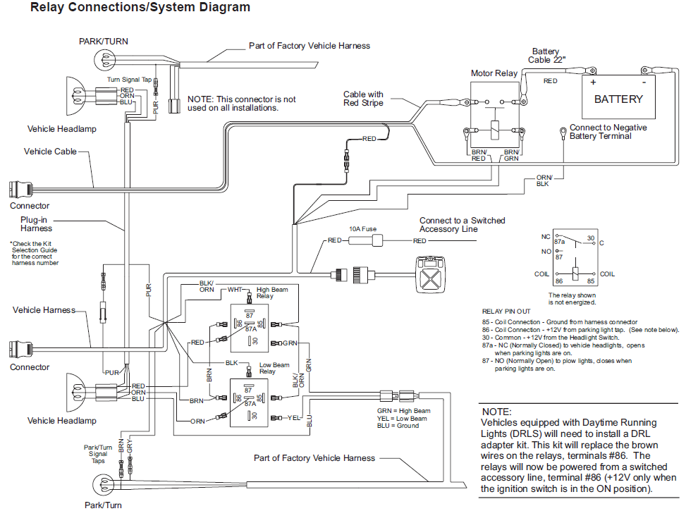
A wiring diagram is a simplified standard pictorial representation of an electrical circuit. Western products has been leading the industry by providing quality snow plows ice control equipment including tailgate spreaders and snow plow accessories. Although intended primarily as a diagnostic tool for headlamp systems the hydraulic system circuitry is also included to show the complete electrical system. Easy to use exploded diagrams provide part numbers and descriptions for all of the equipment listed below. Straight plow hts standard midweight pro plow pro plow series 2 pro plus v plow mvp plus mvp 3 wide outprodigy wide out gen 22018 wide out xl wide out 2017 prodigy. It contains schematics diagrams and charts which supply information for the various types of vehicle and plow headlamp systems.
Once you find the part youre looking for you can add it to a pick list that can be printed and taken to a western dealer where you can request or purchase the part. A wiring diagram is a streamlined standard pictorial representation of an electrical circuit. Assortment of western snowplow wiring diagram. When weight of plow is added. Assortment of western snow plow wiring diagram. A wiring diagram is a kind of schematic which makes use of abstract photographic icons to show all the affiliations of components in a system.
A wiring diagram normally provides details about the family member placement and plan of devices and terminals on the tools to assist in structure or servicing the device. It shows the components of the circuit as streamlined forms and the power and signal links in between the gadgets. Final coupling lug hole center to level surface distance should be 9 12 to 10 12 with plow attached and resting on the level surface. It shows the parts of the circuit as simplified forms as well as the power and also signal links between the tools. Search parts service documentation. A wiring diagram usually offers info regarding the family member position and also arrangement of tools and terminals on the tools to assist in structure or servicing the tool.
Plow transfer quote request. Symbols that represent the parts in the circuit and also lines that stand for the links in between them.
Gallery of Western Plow Wiring Diagram