It shows the elements of the circuit as streamlined forms and the power and signal connections in between the devices. To replace and reconnect a three wire pump.
Wiring Well Pump 220 How To Wire A 220 Well Pressure Switch
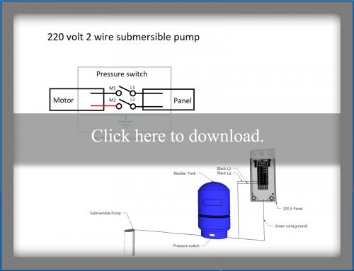
Well pump control box wiring diagram. January 22 2019 by larry a. A wiring diagram is a simplified traditional photographic depiction of an electrical circuit. All well pumps come with a wiring diagram which provide specific instructions for your specific pump. Replace a three wire pump. Collection of submersible pump control box wiring diagram. It shows the elements of the circuit as simplified forms and also the power as well as signal links between the devices.
2 wire submersible well pump wiring diagram a newbie s overview of circuit diagrams. Wiring a pressure switch is simply breaking the circuit power through the pressure switch contacts. Replace the cover on the pressure switch after the zero voltage check and move to the pump control box further downstream. A wiring diagram is a streamlined traditional photographic representation of an electrical circuit. Single phase submersible pump control box wiring diagram 3 wire submersible pump wiring diagram in submersible pump control box we use a capacitor a resit able thermal overload and dpst switch double pole single throw. A very first look at a circuit layout could be complicated however if you can review a subway map you could read schematics.
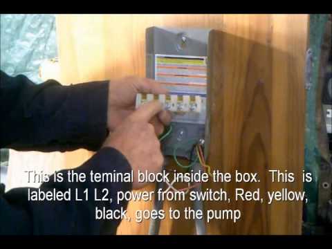
The wiring connection of submersible pump control box is very simple. A wiring diagram usually offers info concerning the relative placement as well as plan of tools and terminals on the devices to help in building or servicing the tool. In most cases if the leads are the same color then the polarity does not matter but check this with the installation sheet and wiring diagram. Collection of 3 wire submersible pump wiring diagram. Most boxes will only show designator marks y r b l1 l2 denoting the pump and incoming wire placement but they may have faded. Here is the complete guide step by step.
Gallery of Well Pump Control Box Wiring Diagram