No open fire or lights. If operating the instrument on power supply units note that the power supply unit must be stabilized and it must comply with the following standard.
C37b7f0 Vdo Tachometer Wiring Diagram 1 Min Wiring Library
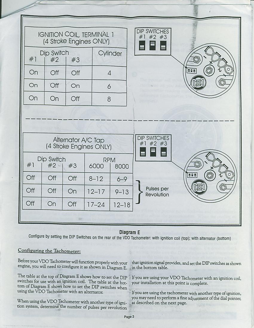
Vdo hour meter wiring diagram. Diagram c shows how to set the switches for diagram d with alternator use this table to calculate pulsesrevolution set switches at this point the installation and wiring of your new vdo programmable tachom the lights in the car and check to see that the instrument and light work properly. Run wires from the quartz clock location through the firewall to. A the positive terminal on the battery after the fuse box but before the ignition switch or any other switch. Din en 61000 parts 6 1 to 6 4. Lamp socket push in wedge type 2 3. Diagram d proper wiring of the vdo quartz clock diagram e wiring examples of the vdo engine hour meter wiring the quartz clock.
If they dont re check your wiring referring to. Diagram a vdo tachometer with hourmeter is programmable from 5 to 200 pulses per revolution vdo vdo item description quantity 1. Always disconnect the battery ground before making any electrical connections. Wiring the gauge illustration a. Route wires from the instrument to. A2c1936250010 universal 2 116 52mm round hourmeter 100k hours led illumination.
Assembly or wiring instructions. 161 or equivalent 2 4. Light bulb 12 volt ge. Oem 10 pack learn more. Connect the harness according to the following wiring matrix. A the battery switched power after the fuse box or user supplied in line fuse 1a b the light switch after the fuse box or user supplied in line fuse 1a c a good dedicated ground location.
According to the electrical wiring diagram.
Gallery of Vdo Hour Meter Wiring Diagram