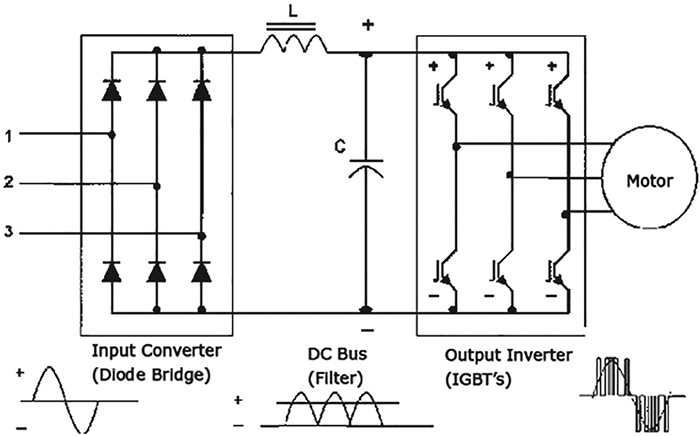
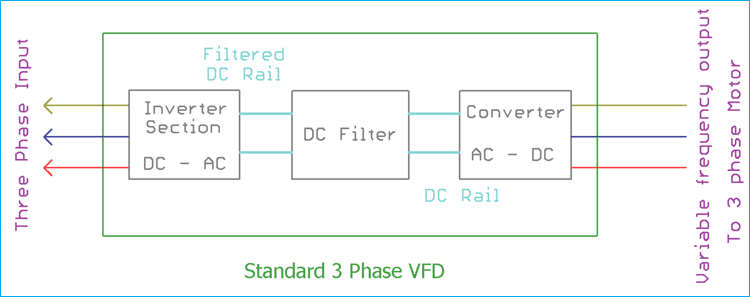
Vfd pwm waveform the diagram below shows a common waveform for a pulse width modulation pwm circuit in the vfd. Learn the basic wiring of variable frequency drives vfd with our electrician steve quist.

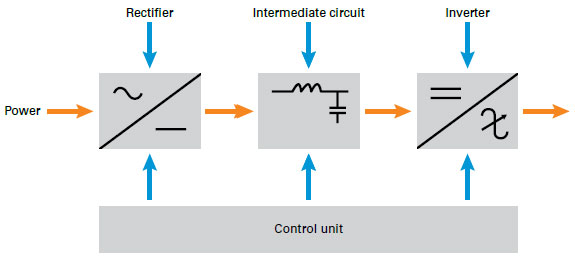
Xx 5518 Drives The Inner Workings Of Ac Drives And Dc Drives
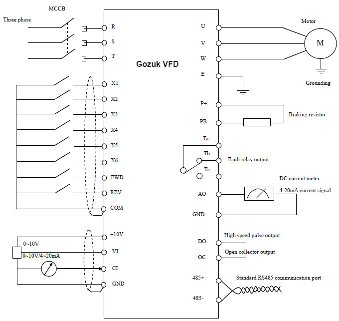
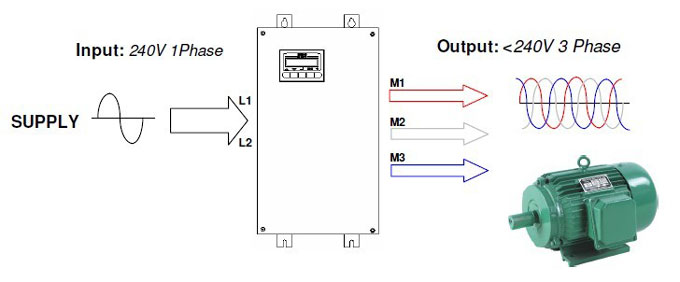
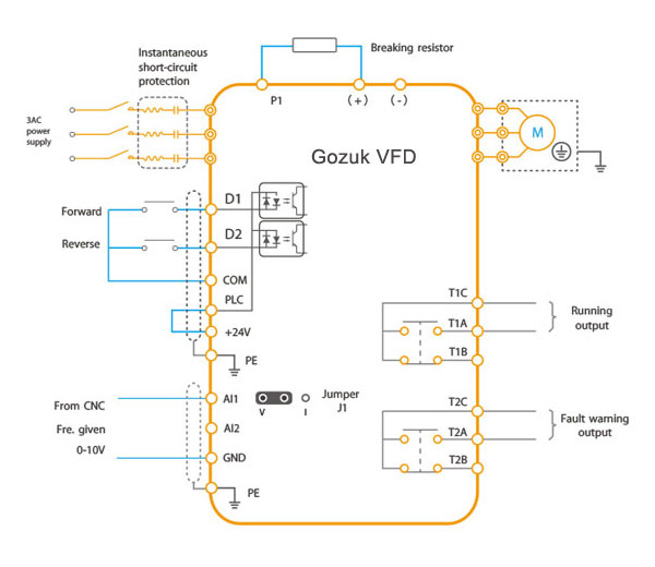
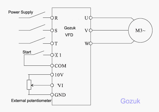
Variable frequency drive wiring diagram. The vfd often called an ac drive or inverter takes a single or three phase signal and varies the speed of a three phase ac induction motor. Steve jordan 124805 views. Running a motor more slowly can save significant energy and speed changes may be useful to the application. Assortment of vfd wiring diagram. Vfd pwm waveform the diagram below shows a common waveform for a pulse width modulation pwm circuit in the vfd. Variable frequency drives wiring diagrams paliha electrical op 1 jun 10 0817.
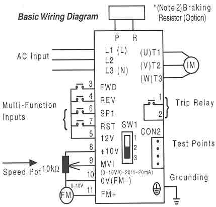
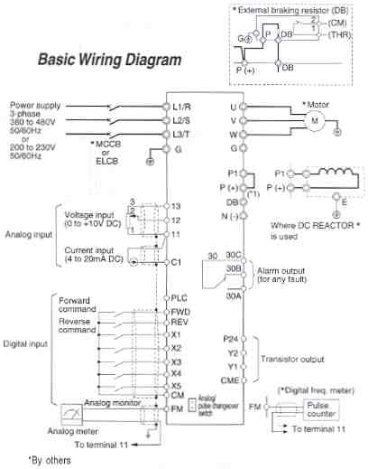
A wiring diagram is a simplified standard photographic depiction of an electric circuit. When a ground fault interrupter is used select the one with no influence for high frequency. If the distance between the vfd and the motor exceeds 250 ft an output reactor should be used between the vfd and the. In this video we used the very popular mitsubishi d700 series vfd showing single phase and three phase wiring instructions. This is the simplest. We strongly recommend using a certified electrician to set up your vfds.
The transistors in the pwm. It shows the parts of the circuit as streamlined forms and the power and also signal links between the gadgets. Vfd inverter drive new 3 phase motor for my myford ml7 lathe duration. This is its main benefit. The vfds showed in the video are the d720s 230v single phase and the d720 230v three phase. I have a problem with selecting between available variable speed dive wiring diagrams especially the location of the main contactor as indicated below 1 no contactor drive is between the feeder mccb and the motor.
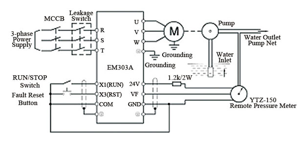
I am here with giving you a vfd start stop wiring diagram for running a vfd through panel board push button and keypad of the vfd it is called hmi. Vfd is a short form of variable frequency drive or variable voltage variable frequency drivethe vfds are working based on changing the input frequency and input voltage of the motor we can change the speed of the. Motor wires from each vfd to its respective motor must be run in a separate steel conduit away from control wiring and incoming ac power wiring to avoid noise and crosstalk between drives. Variable frequency drive wiring accessories mccb molded case circuit breaker do not use a circuit breaker for startstop operation. Vfd start stop wiring diagram. Variable frequency drives explained.
Make sure to connect the ground terminal to an appropriate safety ground. Main circuit wiring variable frequency drive wire input to terminals l1 l2 and l3 for three phase input.
Gallery of Variable Frequency Drive Wiring Diagram