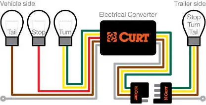
Various connectors are available from four to seven pins that allow for the transfer of power for the lighting as well as auxiliary functions such as an electric trailer brake controller backup lights or a 12v power supply for a winch or interior trailer lights. 4 way trailer connectors are typically used on small trailers such as boat snowmobile utility and other trailers that that do not use brakes.
Wiring Trailer Lights With A 7 Way Plug It S Easier Than You
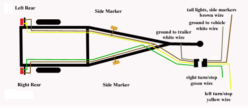
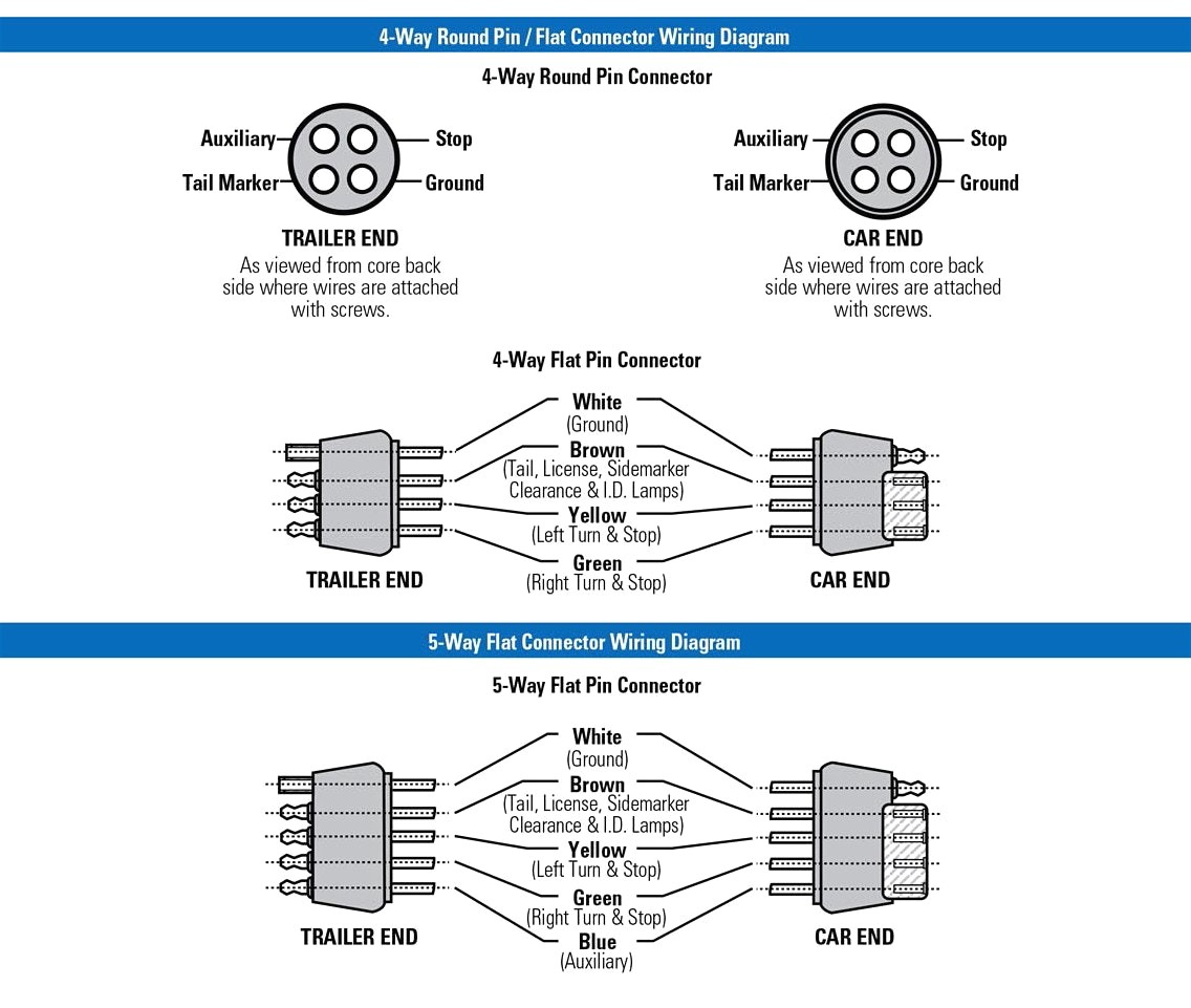
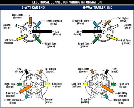
Utility trailer wiring diagram with brakes. A wiring diagram typically gives details concerning the relative placement and also plan of tools and terminals on the devices to assist in building or servicing the device. The four wires control the turn signals brake lights and taillights or running lights. They also provide a wire for a ground connection. Utility trailer 03 4 pin trailer wiring and diagram duration. 34 inch by 1 inch 6 way rectangle connectors right turn signal green left turn signal yellow taillight brown ground white. The red and blue wire can be used for brake control or auxiliary.
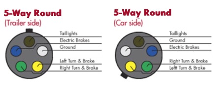
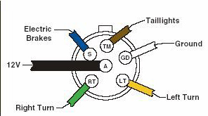
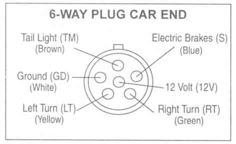
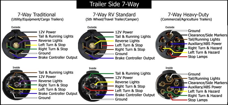
Use on a small motorcycle trailer snowmobile trailer or utility trailer. 7 way trailer wiring diagram is explained in details in the picture and the table below. Collection of wiring diagram for utility trailer with electric brakes. It reveals the elements of the circuit as streamlined forms and also the power and signal connections between the gadgets. On most recreational vehicles. Blue electric brakes or hydraulic reverse disable see blue wire notes below in the trailer wiring diagram and connector application chart below use the first 5 pins and ignore the rest.
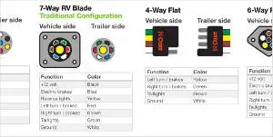
A wiring diagram is a streamlined conventional pictorial representation of an electric circuit. 1 4 wire the first 4 pins white brown yellow green just like the 4 pin connector above. Trailer wiring diagrams trailer wiring connectors. It reveals the parts of the circuit as streamlined forms as well as the power and signal connections in between the gadgets. It may transfer power better therefore the connector is suggested for higher level electric in the vehicle. White pin for the ground.
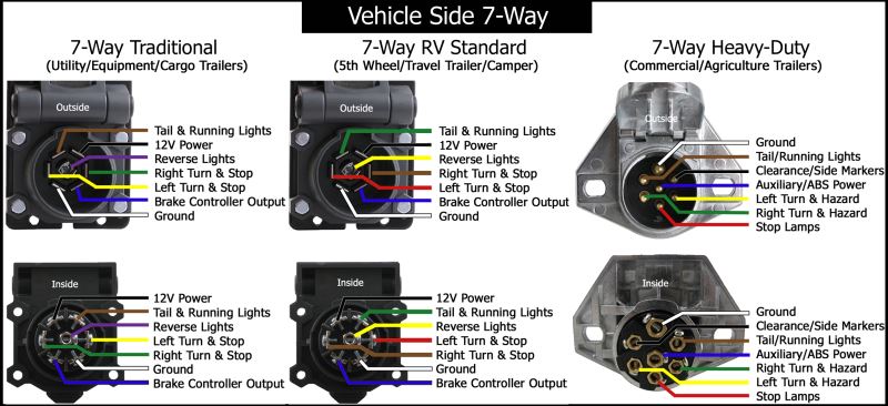
Here is the diagram for 7 pin connector. Large 5th wheel trailers. Assortment of electric trailer brake wiring schematic. 7 way trailer connectors are used by the following vehicle types. 7 pin trailer wiring diagram with brakes. Various connectors are available from four to seven pins that allow for the transfer of power for the lighting as well as auxiliary functions such as an electric trailer brake controller backup lights or a 12v power supply for a winch or interior trailer lights.
As the name implies they use four wires to carry out the vital lighting functions. This utility trailer wiring diagram with brakes model is more appropriate for sophisticated trailers and rvs. Traditional trailer with brakes use a 5 pin connector. Choose a connector that has the required number of pins for the functions required for your trailer. How to build a diy utility trailer for cheap. Can also be used as custom wiring on trailers with 3 lightwire systems.
4 way trailer connectors are. Trailer wiring electric brakes tip. A wiring diagram is a streamlined traditional pictorial representation of an electrical circuit.
Gallery of Utility Trailer Wiring Diagram With Brakes