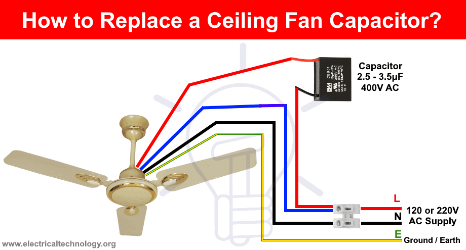
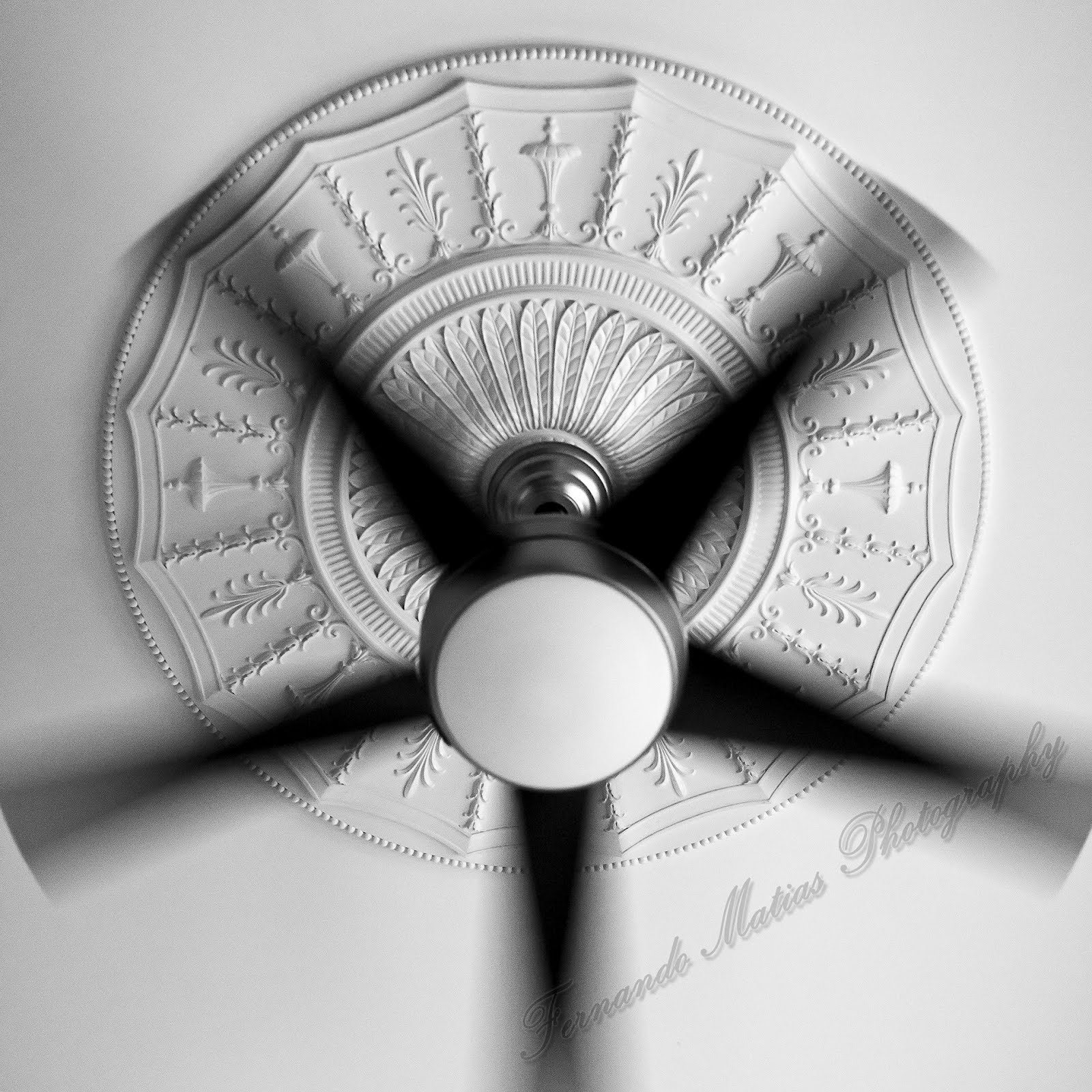
Our new range of ceiling fans is inspired by the lotus known for its dirt and water repelling qualities. Ceiling fan wiring diagram 2.
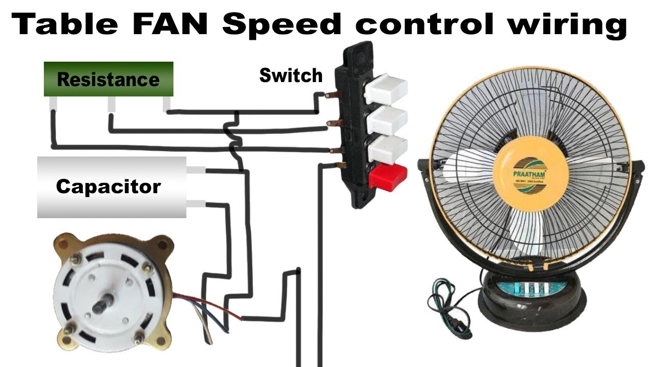
Table Fan Speed Control Wiring
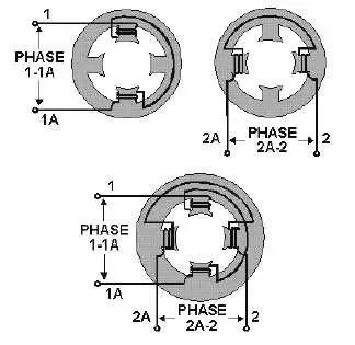
Usha ceiling fan wiring diagram. It shows the components of the circuit as simplified shapes and the knack and signal associates amid the devices. Speed switch connection table. Connect the black wire to the screw located in swith 1. 1 to l and c1 1 2 med. Need step by step instructions on replacing ceiling fan. Black speed switch three wire capacitor.
Twist the copper ends of the wires together to connect them together. The fan and a lighting assembly. In the switch box. This wiring diagram illustrates the connections for a ceiling fan and light with two switches a speed controller for the fan and a dimmer for the lights. Leave the green or copper wire thats coming out the ceiling unattached for now. Wire a ceiling fan within usha ceiling fan wiring diagram image size 454 x 328 px and to view image details please click the image.
Connect black fan wire to the black ceiling wire. A range of fans that keeps dust at bay goodbye dust fans. At usha we have always been inspired by nature. Pick the diagram that is most like the scenario you are in and see if you can wire up your fan. 1 to l and c1 2 3 slow. Connect the blue wire to the red wire.
Here we will describe the wire colors as according to the wiring color codes for the usa and canada. Thus before trying to install a ceiling fan make sure to use the correct wiring diagram for your specific fan in your region. With these diagrams below it will take the guess work out. This might seem intimidating but it does not have to be. Light and portable but highly effective the table fans let you reach those tight hot corners of the house where centralized conditioning or air cannot reach. 1 to l c1 1 and c1 2.
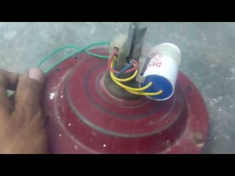
This range of ceiling fans are a dream come true where the trusted iconic usha fan meets chandeliers in the fontana range to avant garde designs in the hunter series to name just two. Black speed switch with only three terminals connected two wire capacitor. Coated with superior polyurethane lacquer our fans resist the accumulation of dirt. Ceiling fan wiring diagram 1. Here is a picture gallery about usha ceiling fan wiring diagram complete with the description of the image please find the image you need. Take a closer look at a ceiling fan wiring diagram.
Typically a green wire is attached to your fan bracket and the other green wire is attached to the fan itself. Connect white wires together. Usha ceiling fan wiring diagram wiring diagram is a simplified usual pictorial representation of an electrical circuit. Connect the red wire to the screw in switch 2. The lotus stays pristinely clean at all times. From the switches 3 wire cable runs to the ceiling outlet box.
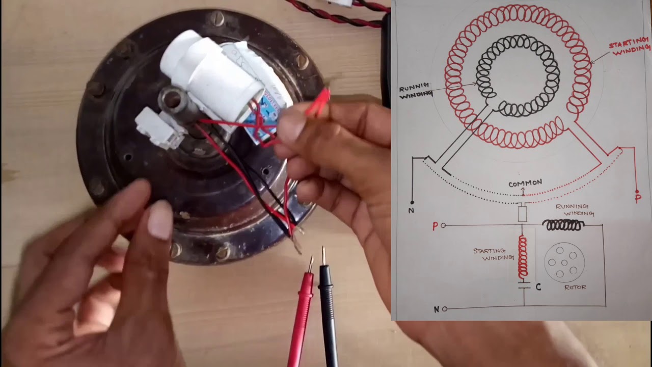
Split the incoming hot wire into a y and connect it to a terminal on each switch. A ceiling fan usually consists of two main parts. The source is at the switches and the input of each is spliced to the black source wire with a wire nut.
Gallery of Usha Ceiling Fan Wiring Diagram