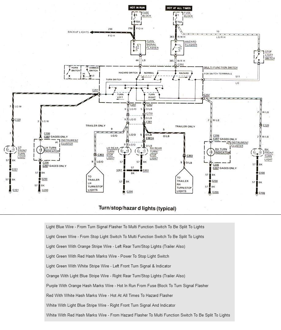
It doesnt make any difference as the tail light wiring isnt affected. Flashers and hazards turn signal flasher wiring diagram wiring diagram contains numerous comprehensive illustrations that display the link of varied products.
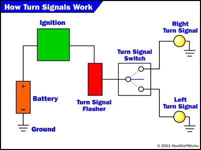
The Wiring How Turn Signals Work Howstuffworks
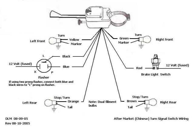
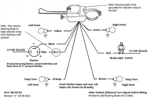
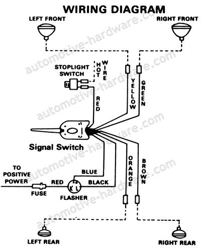
Turn signal wiring diagram. Then you just attach the wires to the correct points as indicated by the manual or wiring diagram. A wiring diagram is a streamlined standard pictorial depiction of an electric circuit. Collection of chevy turn signal switch wiring diagram. If not the structure wont work as it ought to be. You can get them at places like napa or here. Turn signal head light switch flasher red red red red red blue white blue black black black black brown x l p the turn signal alarm red wire connects to the blue p terminal on the flasher.
Turn signal flasher wiring diagram led turn signal flasher wiring diagram motorcycle turn signal flasher wiring diagram turn signal flasher circuit diagram every electric arrangement consists of various unique parts. I had many responses and have collected them in the pages that follow. In addition i browsed the net and found a few more. It shows the parts of the circuit as simplified forms and also the power and also signal links in between the devices. Turn signal wiring diagrams recently i asked on fordbarn if anyone had wiring diagrams for the particular turn signal system everlasting that i have mounted on my 29 tudor. They will combine the brake wiring and the turn signal wiring so they will work.
Some have the tail light wire running through them 4 wire into 3 wire and some dont 3 wire into 2 wire. The black alarm wire connects to the white turn alarm turn signal wiring signal head wire. Wellborn variety of universal turn signal wiring diagram. Lets take a look at how the turn signal circuit is hooked up. From there it goes to the stalk on the steering column. It reveals the parts of the circuit as simplified shapes and the power and signal links between the tools.
Comes with two toggle switches one for hazard and one for turn signals. The turn signal circuit gets power when the ignition key is on. The power goes through a fuse panel into the thermal flasher. March 16 2019 by larry a. A wiring diagram is a streamlined conventional pictorial depiction of an electrical circuit. This self canceling turn signal system from haywire in joplin mo is programmable and easy to install.
It includes instructions and diagrams for various kinds of wiring strategies and other things like lights home windows and so on. Unfortunately i didnt retain the sources. Each part should be placed and linked to other parts in specific way. They look like this.
Gallery of Turn Signal Wiring Diagram