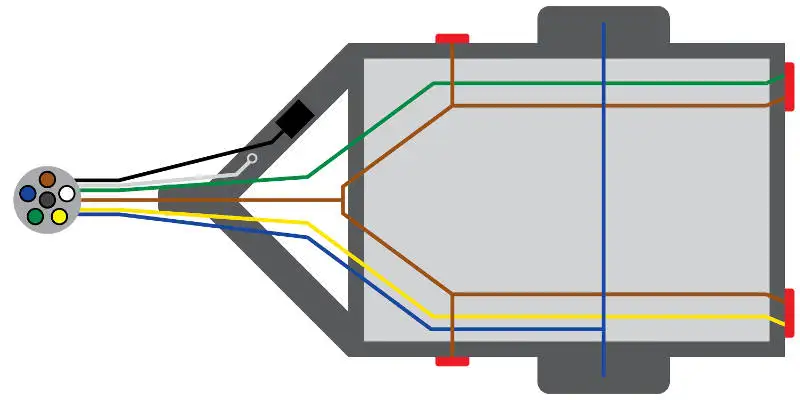
To connect the electric system of your trailer to the vehicle you will be using special connector. Also it must connect with things if included that use the aux power and back up lights too.
Trailer Wiring Diagrams Johnson Trailer Co
Trailer pigtail wiring diagram. Trailer wiring diagrams trailer wiring connectors various connectors are available from four to seven pins that allow for the transfer of power for the lighting as well as auxiliary functions such as an electric trailer brake controller backup lights or a 12v power supply for a winch or interior. 4 pin trailer wiring diagram. This trailer pigtail wiring diagram version is more acceptable for sophisticated trailers and rvs. Tractor trailer pigtail wiring diagram 7 way tractor trailer plug wiring diagram 7 way truck trailer plug wiring diagram chevy truck trailer plug wiring diagram people today understand that trailer is a vehicle comprised of very complicated mechanics. The trailer wiring diagram shows this wire going to all the lights and brakes. We have an excellent wiring diagram on our website i will provide you a link so you can look at it.
It can transfer electricity better hence the connector is suggested for higher level electric in the car. Wiring diagram for 7 prong trailer plug 7 way semi trailer plug throughout trailer pigtail wiring diagram image size 500 x 250 px and to view image details please click the image. As the name implies they use four wires to carry out the vital lighting functions. They also provide a wire for a ground connection. Trailer wiring diagrams 4 way systems. Above we have describes the main types of trailer wiring diagrams.
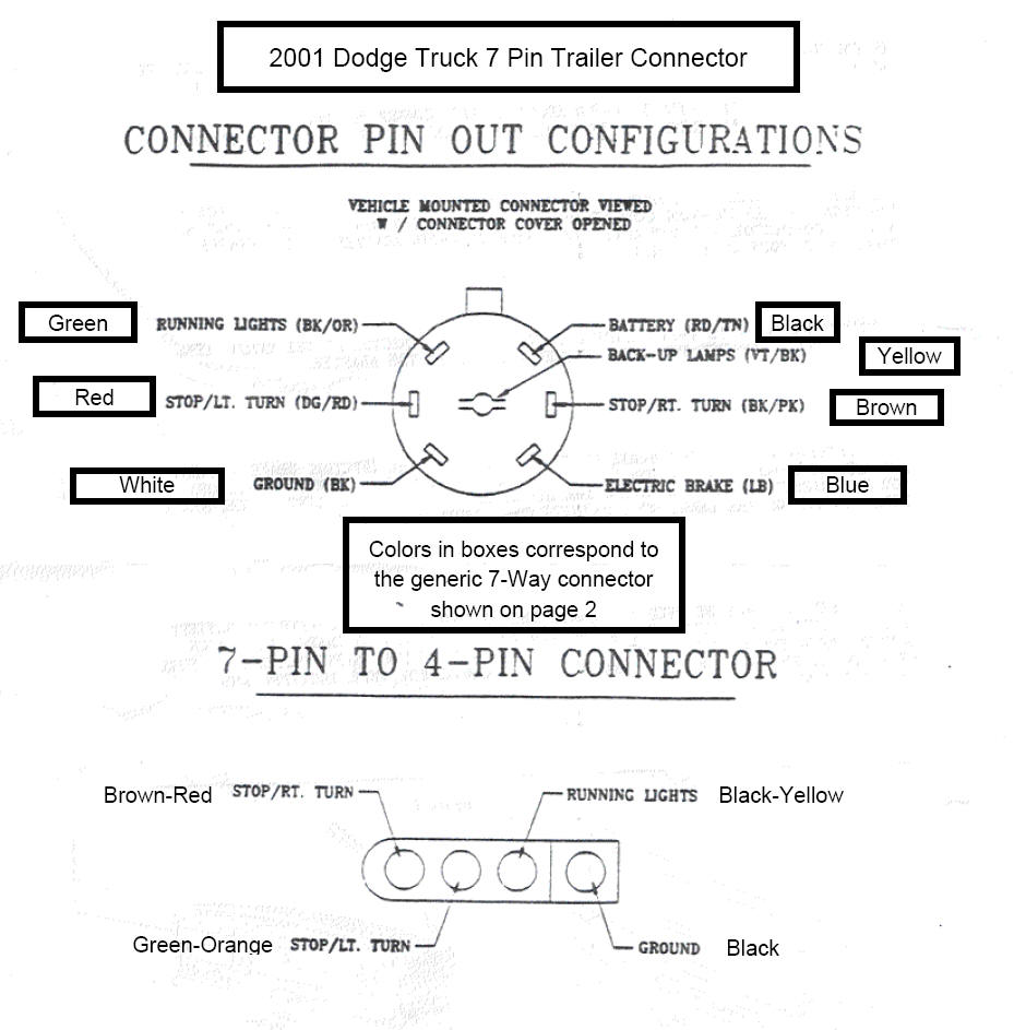
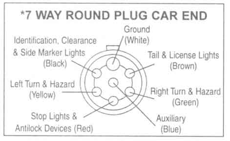
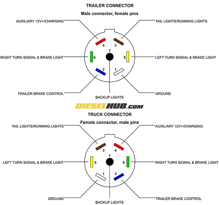
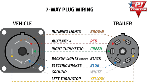
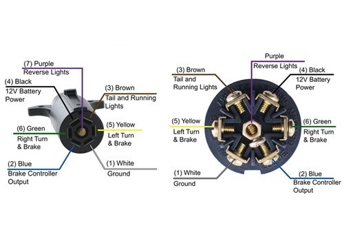
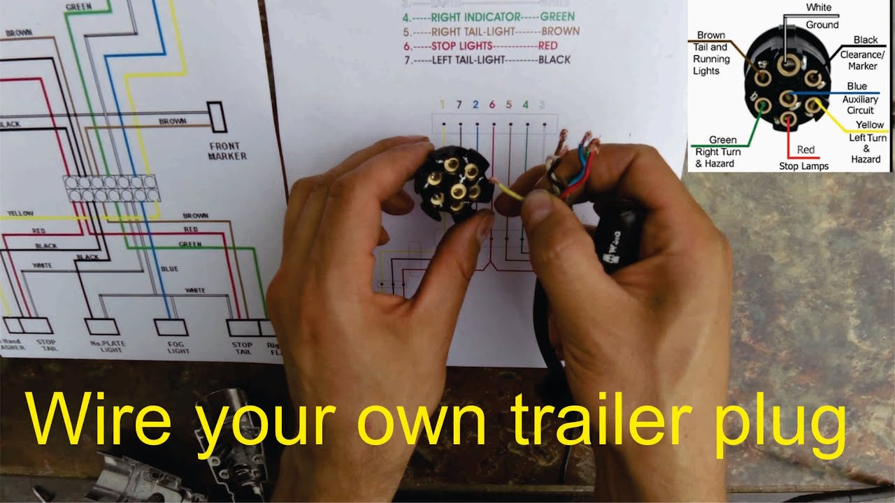
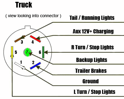
The four wires control the turn signals brake lights and taillights or running lights. White pin to your ground. 4 way flat molded connectors allow basic hookup for three lighting functions. Some trailer builders just connect this wire to the frame then connect the ground from all the other lights and accessories to the frame as well. When wiring a trailer connector it is best to wire by function as wire colors can vary. Heres the diagram for 7 pin connector.
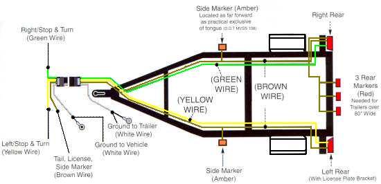
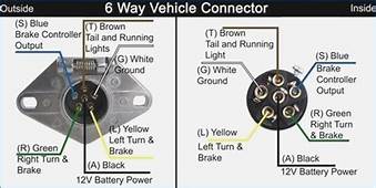
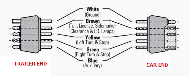
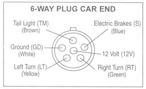
Here is a picture gallery about trailer pigtail wiring diagram complete with the description of the image please find the image you need. Complete with a color coded trailer wiring diagram for each plug type this guide walks through various trailer wiring installation solution including custom wiring splice in wiring and replacement wiring. If your vehicle is not equipped with a working trailer wiring harness there are a number of different solutions to provide the perfect fit for your specific vehicle. 4 way trailer connectors are. Right turn signal stop light green left turn signal stop light yellow taillight license side marker brown and a ground white. 4 way trailer connectors are typically used on small trailers such as boat snowmobile utility and other trailers that that do not use brakes.
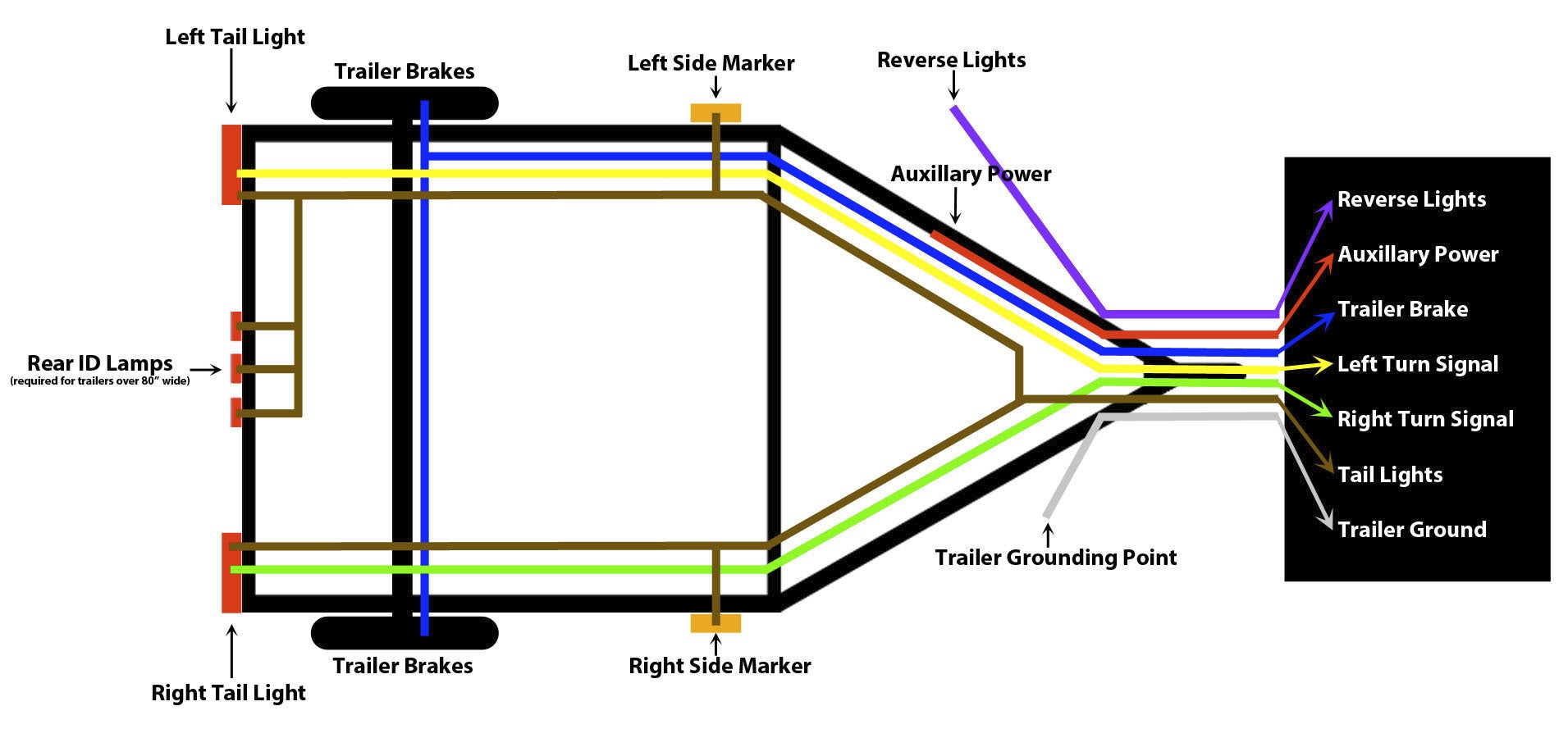
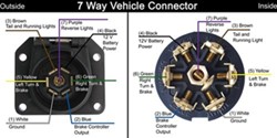
Below is the generic schematic of how the wiring goes. This vehicle is designed not only to travel 1 place to another but also to take heavy loads. If you are looking at the inside of the trailer connector where the wires mount to the terminals starting at the top and rotating clockwise.
Gallery of Trailer Pigtail Wiring Diagram