Throttle position sensor tps wiring diagram part 2 throttle position sensor tps diagnostictroubleshooting notes. Throttle position sensor wiring diagram dodge throttle position sensor wiring diagram ford throttle position sensor wiring diagram gm throttle position sensor wiring diagram every electric structure is composed of various different components.

28 Accelerator Pedal Position Sensor Wiring Diagram Wiring
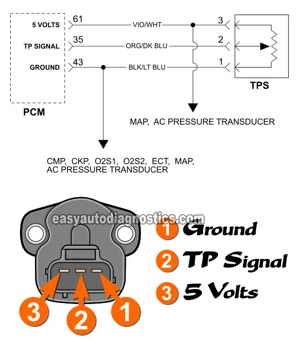
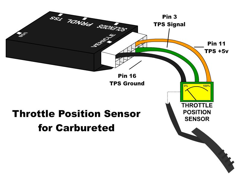
Tps sensor wiring diagram. Most throttle position sensors have at least 3 wires. Using jumper wires and high impedance voltmeter test between the sensor ground and reference terminals the voltage should be approximately 5 volts. Black is ground and should be tapped into the black main ground wire from vehicle pin 16 orange is the 5 volt reference. Using a t pin carefully slide the t pin into the signal wire connection. If youre testing for a short to ground a short to power or an open in this circuit then youll need to unplug all of the sensorscomponents this sensor ground wire connects to. F150 f250 f350 crown victoria e150 e250 e350.
If the sensor passes this test perform the same test at the computer using the wiring diagram to locate the tps signal wire pin. Remove the two tps sensor mounting screws then pull the tp sensor out of the throttle body housing. The wiring harness for the throttle position sensor is contained in the main wiring harness and is well protected except for the short part of the harness that leads from the main harness to the throttle position sensor its pigtail. Brnwht wires feeds the tps 5 volts dc. Search for throttle position sensor wiring diagram here and subscribe to this site throttle position sensor wiring diagram read more. The gryred wire feeds ground.
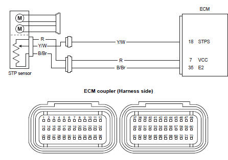
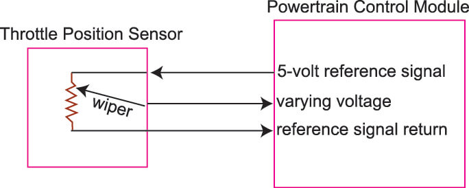
Each part ought to be placed and linked to different parts in particular manner. The wiring harness on a vehicle seldom malfunctions unless the wires rub against something or an animal chews through the wires. These are for a 5 volt reference a return line and the actual tps voltage line. When testing the throttle position sensor system always make sure you have the 5 volt reference and return and then monitor the signal line for actual voltage output from the throttle position sensor. The pcm provides a sensor ground on the grnblk wire to a total of 6 components including your civics throttle position sensor. If the voltage is not the same at the computer as it was at the sensor repair the wire.
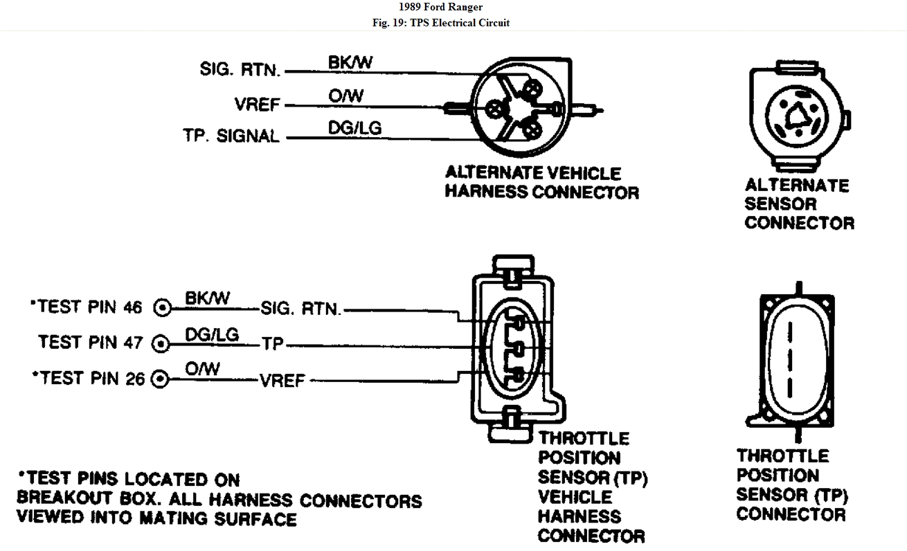
Ford throttle position sensor connections ford has two different color codes for throttle position sensors and several different connectors and pin outs. The grywht wire carries the tp signal to the pcm. Disconnect the negative battery cable. Throttle position sensor tps wiring diagram 1997 1998 ford 46l 54l. The early style color code mostly matches the wiring of our harnesses. Find your throttle position sensor wiring diagram here for throttle position sensor wiring diagram and you can print out.
Common throttle position sensor tps wiring diagram wire color terminal identificationlocation may vary on certain models fig. Disengage the wiring harness connector from the tp sensor. Otherwise the arrangement wont work as it ought to be. Throttle position sensor replacement removal installation.
Gallery of Tps Sensor Wiring Diagram