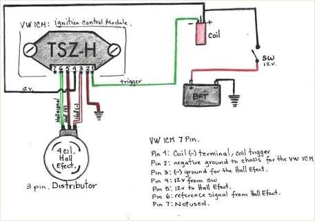
Howzit guys i have the standard dicktator wiring on my 20v converted car with the module built into the coil my timing kept jumping. It has 7 pins and 4 wires.

Download 12 Volt 3 Pole Switch Wiring Diagram
Tp100 module wiring diagram. There are 2 wiring methods for the rtd module and pt100 temperature sensors two wire and three wire connections. Connecting a tacho adapter. Additional diagrams notes. Placement of the module varies from model to model so check the appropiate service manual of your vehicle for the exact location. Aftermarket tp100 ignition module of high quality built by dicktator with high qulaity electronic igfet components. I was advised that the coilmodules causing it i was told that i rather change to wasted spark and add the bosch coil pack and tp100 i need the correct wiring diagram for the tp100 as the 1 thats shown on the dicktator site under wasted spark diagram doesnt.
Multi tooth wiring diagram and installation notes. Tp100 ignition module short redyellow hall ve brown rev counter input hall v ignition 12v 0 5 green magnetic dissy toyota honda etc or fiat uno crank trigger magnetic ve thick red purple 1mm black water temp 5v supply greyred or greyblue signal ground black as seen from component side 1mm black green. Refer to the diagram below and check that the belt tension is within 3mm. Fit the tiller connector e02607 into the end of the push rod e02522 and screw in finger tight. View and download simrad tp10 user manual online. Afx airfuel monitor manual.
The bearing with the two screws. Use a wiring diagram for the year model of your vehicle. Locate the terminals running into and out of the ignition module. Alright guys while changing the gle fuel filter i mistakely pulled off the 3 wires coming from the distributor to the tp100 module or something. Installation manual for the afx airfuel monitor. These modules have no internal electronic rev limiter such as the vw tp100 modules and are compatible with any engine management system aftermarket or standardfor eg.
Hall effect pcbfit the hall effect pcb onto the 2 pillars using 2 nylon washers. One wire is grounded to the body pin 2 from the right thats fine the other 3 i have no clue how to wire. Instructions for fitting launch control. Tp10 marine equipment pdf manual download. A1b1 a2b2 and c1c2. When wiring with two wires first jumper across a1 and b1and a2 and b2 respectively then connect pt100 sensors and to the rtd module according to the following diagram on the left.
Instructions for fitting a tacho adapter.
Gallery of Tp100 Module Wiring Diagram