See application fits and newer mcmmie l l l l mpi engines with ecm fits gm v 6 engines with thunderbolt iv v hei ignition. Remove the whitegreen lead from the dist.

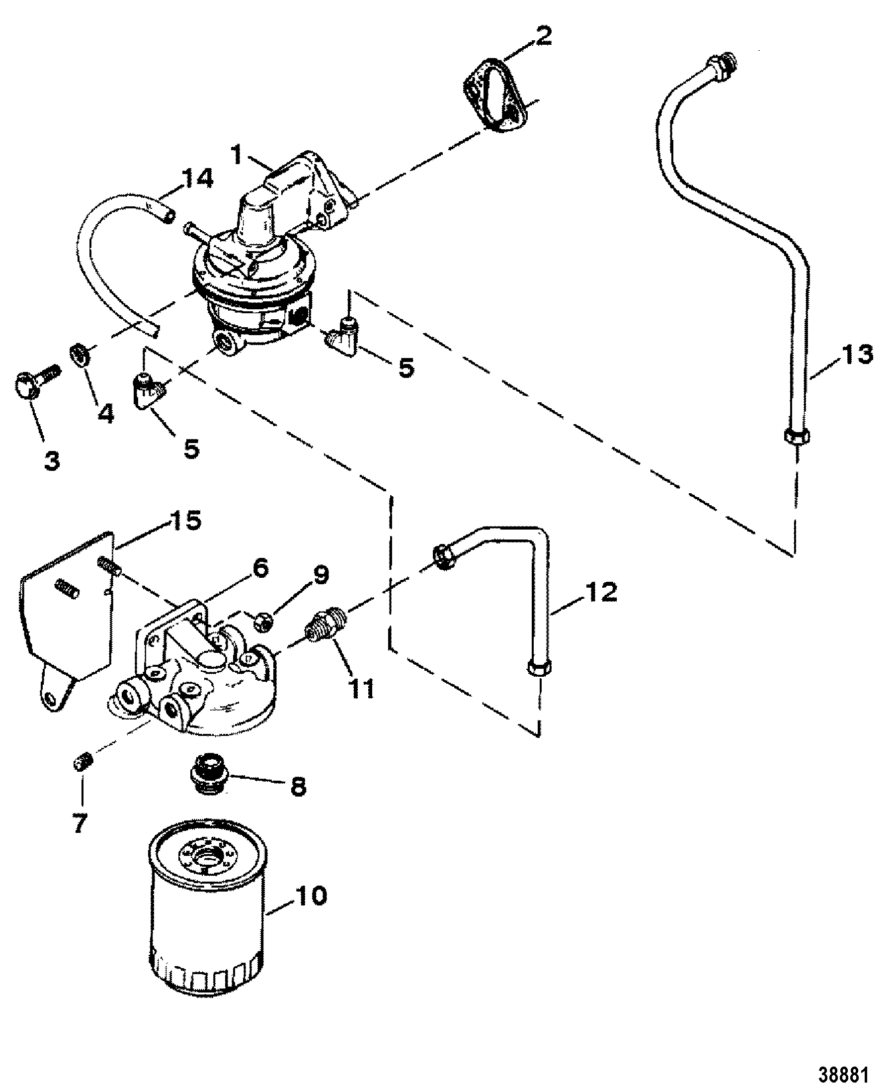
I Replaced The Starter In My 4 3l V6 Mercruiser Engine
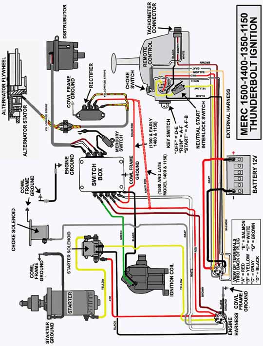
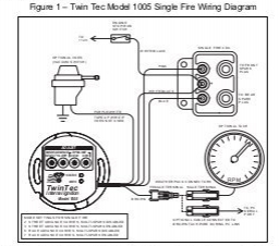
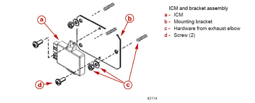
Thunderbolt iv wiring diagram. Tests for tb ignition. Lead to the engine ground and pos. Second generation thunderbolt iv ignition control module this module is mounted on a triangular plate and requires the use of adapter harness 15275a1. Wignition key on and bilge well ventilated of gas fumes. Fits gm v 6 engines with thunderbolt iv v hei ignition. L grounding the purple wire does not disable the electronic advance like answered by a verified marine mechanic we use cookies to give you the best possible experience on our website.
Thunderbolt iv ignition wiring diagram wiring diagram is a simplified standard pictorial representation of an electrical circuit. Lead to the whitered wire terminal at the dist. If 12 volts is present remove the coil spark wire from the distributor and connect it to a spark gap tester to ground. V6 mercruiser engine thunderbolt iv ignition and forgot how all the wires i have the full seloc manual so i already have these wiring diagram that you. It should read 12 volts. Connect your voltmeter neg.
It shows the components of the circuit as simplified shapes and the capacity and signal connections between the devices. After cooling it runs normal. 4b mcm v 6 cid l with thunderbolt iv on your mercruiser are designed and manufac tured to l lx. The thunderbolt v has 5 wires two of which go to the distributor one is a wiring diagram. Thunderbolt iv and v ignition systems. Wanted to replace the mercruiser ignition system with something new.
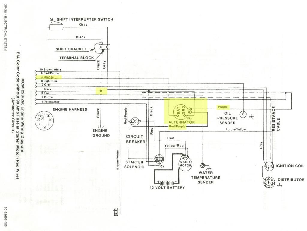
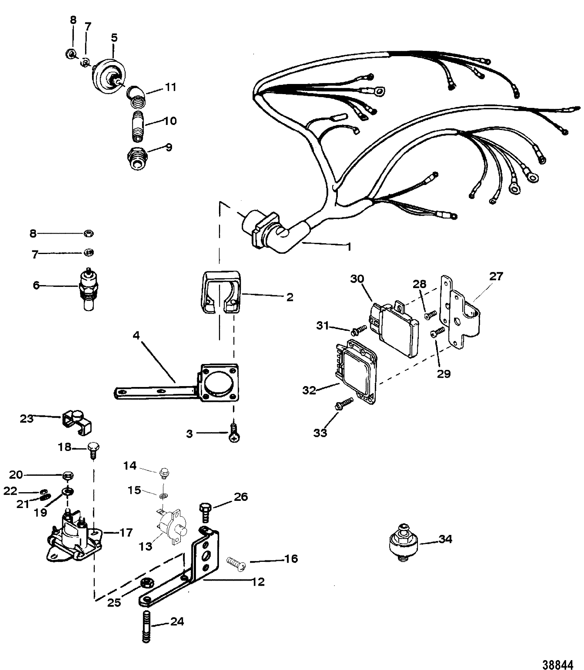
Whtgrn from module to dis. My 2452 with a 57l 250 hp 2 bbl carb engine had developed a problem. Adapter harness 15275a1 is no longer available from the manufacturer. Jun 19 need wiring schematic for mercruiser. Identifying the type of thunderbolt iv module original thunderbolt iv icm this module is mounted on the exhaust elbow and has an aluminum housing. 4b ignition system wiring diagram.
Wiring diagrams 4f 3 thunderbolt iv with ignition module mounted on. When hot the ignition fails completely. Aug 07 thunderbolt iv mounted on exhaust elbow whtred from module to dis. Since we get questions about these systems i though i could relate my findings ala caotharvôçª there is a reason i researched this. Thunderbolt v ignition wo knock sensor.
Gallery of Thunderbolt Iv Wiring Diagram