The formulated quality standards exceed european standard en1646. Cut the connection when the step is fully extended.

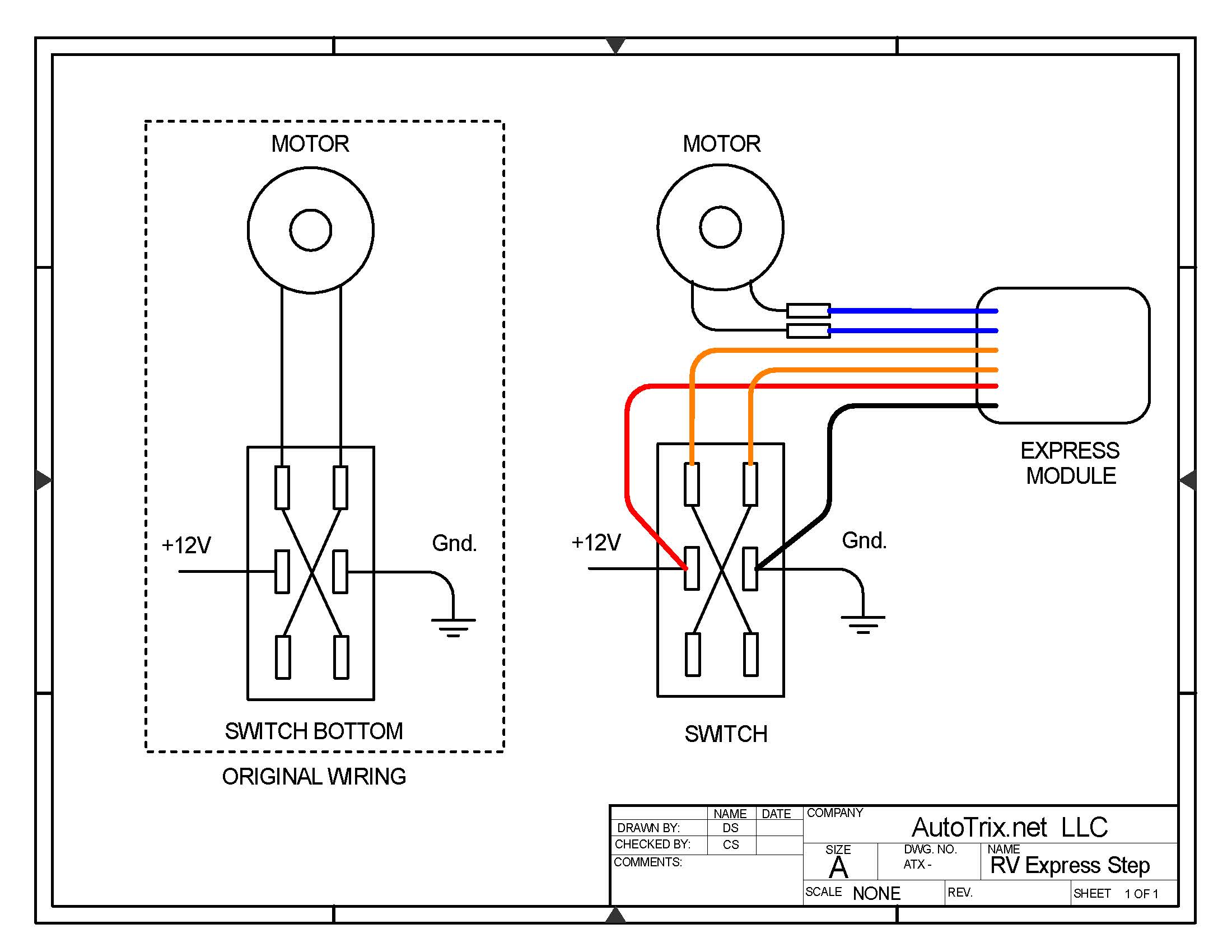
Wiring Diagram For Omnistep
Thule step wiring diagram. A warning light l that is turned on if the step is not fully retracted and the engine is running can be connected to this switch according to the wiring diagram. Motorhome steps from thule give you easy safe entry to your vehicle with a choice of manual or motorised operation. 1 extend the step connect the thule step motor to a 12v dc battery. Follow the wiring diagram for all electrical installation. Hi all some kind soul posted a wiring diagram for an omnistep recently. He also explained all its little foiblessnags etc.
Battery negative is connected to terminal 4 of the switch and comes back out of the switch at terminal 5. Firstly the system is designed to retract the step and sound the alarm should you start your engine with the step extended. Spare parts use the product finder below to find the spare parts instructions and fit kits you need. A switch for the connection of an optional warning lamp in the vehicle is supplied as standard making it. Do not keep the thule step motor under tension for more than 2 3 seconds. Jan 8 2013 4153 4187 dronfield derbyshire funster no 24202 mh burstner lyseo 690g exp happy flt for 8 years apr 9 2016 1 the stop switch has packed up when i take in the step.
Repairing stuck motorhome steps kwikee steps travel supreme rv duration. Thule single step 12v 460 model number. Under this condition the control switch is as shown in switch picture a. Thule omni step automatic sliding step 400mm duration. It was done in a manner even a numpty like me could understand. Start date apr 9 2016.
For keys locks click here. Install the thule step in a dismountable way. Does anyone have a description diagram for replacing it. 3 connect a warning light a switch s2 which is pushed in when the step is retracted is incorpo rated in the thule step. Floyd turbo 25315 views. Saved it to compbut lost it when had comp probs.
Go to cart continue shopping choose your stroller features conform to the emv and ce standards. Choose your ideal step here. Unable to find it on forum. Place the purple wire on the positive pole and the orange wire on the negative pole. Nowadays the information on clives website may well be out of date and you would be better to provide your auto electrician with copies of the manual slideoutstep12v and manualrelayfor step12v user manual files that include a wiring diagram for the current thule product that can be downloaded from the thule website via.
Gallery of Thule Step Wiring Diagram