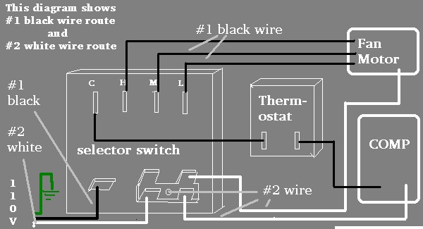
The fan will not blow in the fan on position. 2 5 bnfc x1 h1 x2 x3 h2 h3 x0 3 2 1 3 2 1 3 2 1 connect connect primary primary inter secondary.
220 240 Wiring Diagram Instructions Dannychesnut Com
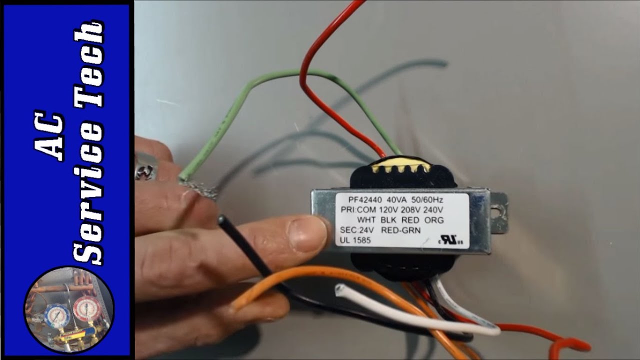
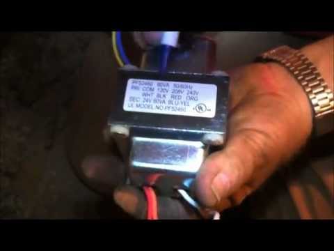
Tfm4031 transformer wiring diagram. International refrigeration products low voltage universal transformer tfm4031. The schematic for the circuit will be available in the product information or on the website of the circuit manufacturer. In this lecture well examine transformer winding polarity transformer power ratings rated voltage rated current parallel winding configurations series aiding and series opposing winding. If your transformer is shot weak or noisy then you might want to consider a new transformer. Beautiful hevi duty transformer wiring diagram adornment. 90 t40f3 from white rodgers at allied electronics automation.
White rodgers 90 t40f3 transformer 40va 60 hz 120208240v primary 24v secondary foot mount for industrial heating and air conditioning controls applications features color coded primary leads multi mount styles available. The transformer shows how it should be wired on the label. Where ever there is a connection to a wire there is a potential problem. The white wire is the common and for 120 volts. However it is always best to obtain a schematic of the circuit containing the transformer to determine how it is connected. Nothing works on your heating air conditioning system.
The tfm4031 universal low voltage transformer will work on 120 208 or 240 volt applications. 240 volts delta secondary. Class ii transformer 40va 120 208 240v primary 24vac 167a secondary 90 series. The tfm4031 universal transformer transforms 110 or 240 volts ac into 24 volts ac so that the low voltage components on the furnace and air conditioner can operate. The wiring should be clearly labeled on the transformer. Hvac transformer wiring diagram download.
Electrical transformer wiring diagram gallery collections of electrical transformer wiring diagram new isolated ground. You can check the voltage on most control boards between the c com and r red terminals to determine if the low voltage transformer is operating correctly. Hvac transformer wiring diagram inspirationa wiring diagram auto. Below is diagram of the 24 volt system. Wiring diagram book a1 15 b1 b2 16 18 b3 a2 b1 b3 15 supply voltage 16 18 l m h 2 levels b2 l1 f u 1 460 v f u 2 l2 l3 gnd h1 h3 h2 h4 f u 3 x1a f u 4 f u 5 x2a r power on optional x1 x2115 v 230 v h1 h3 h2 h4 optional connection electrostatically shielded transformer f u 6 off on m l1 l2 1 2 stop ol m start 3 start start fiber optic.
Gallery of Tfm4031 Transformer Wiring Diagram