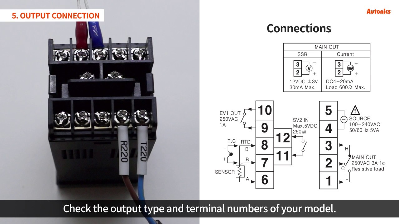
1 for thermocouple tctc 6 7 8 910 thermocouple 1 for two wire pt 100. Most content included in online help.
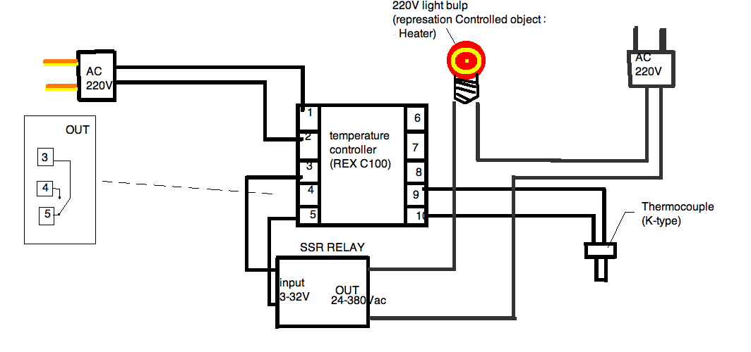
Help Me Wire A Heater And Controller
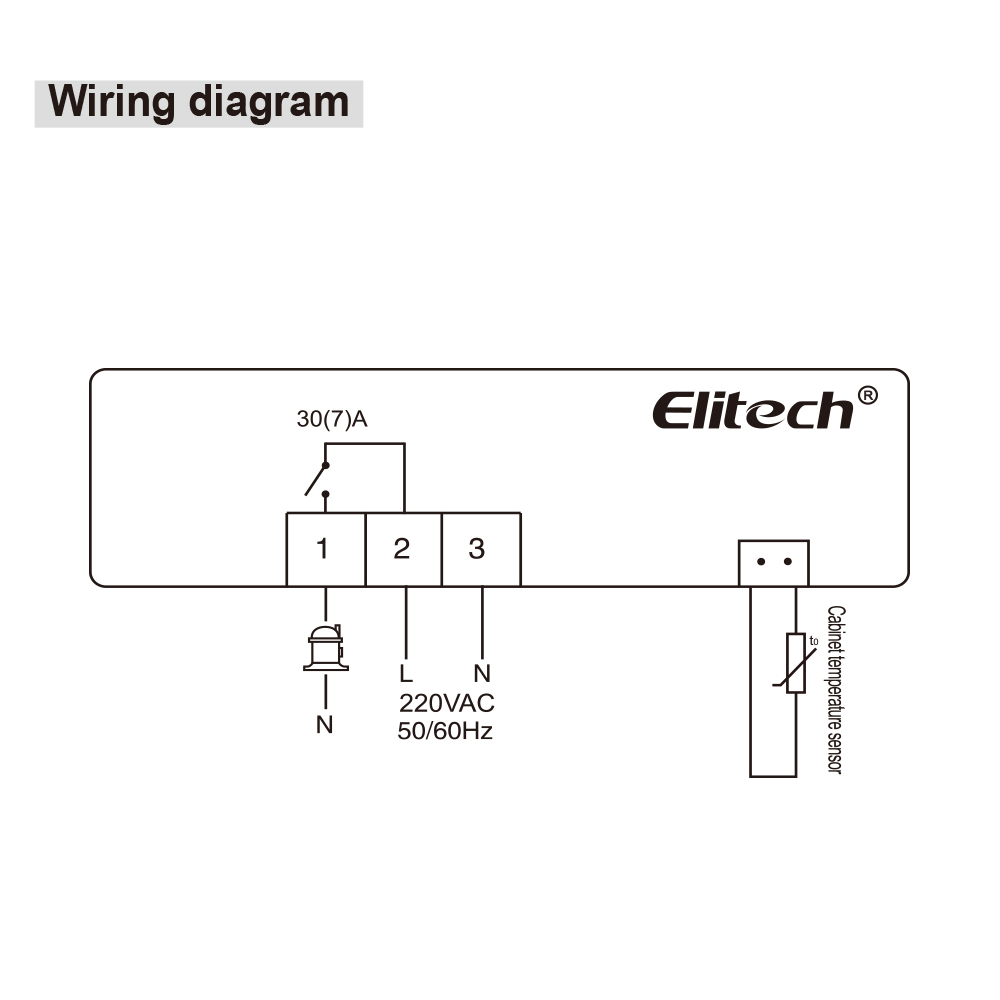
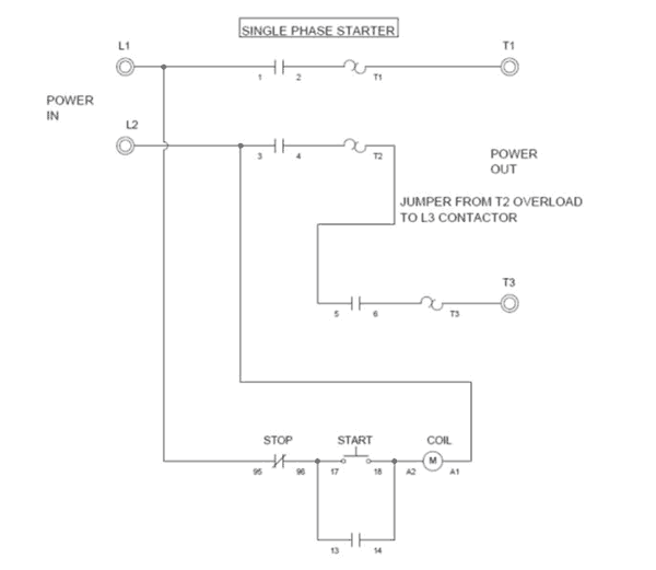
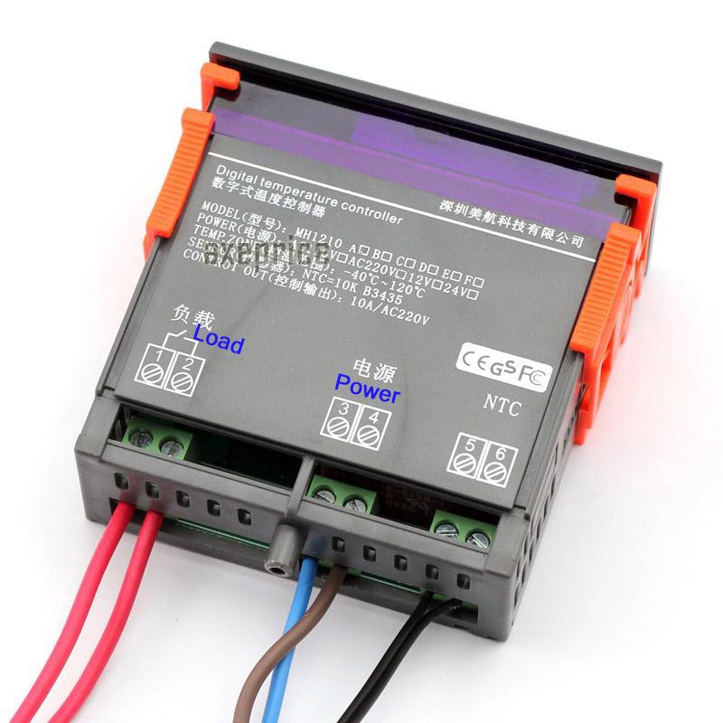
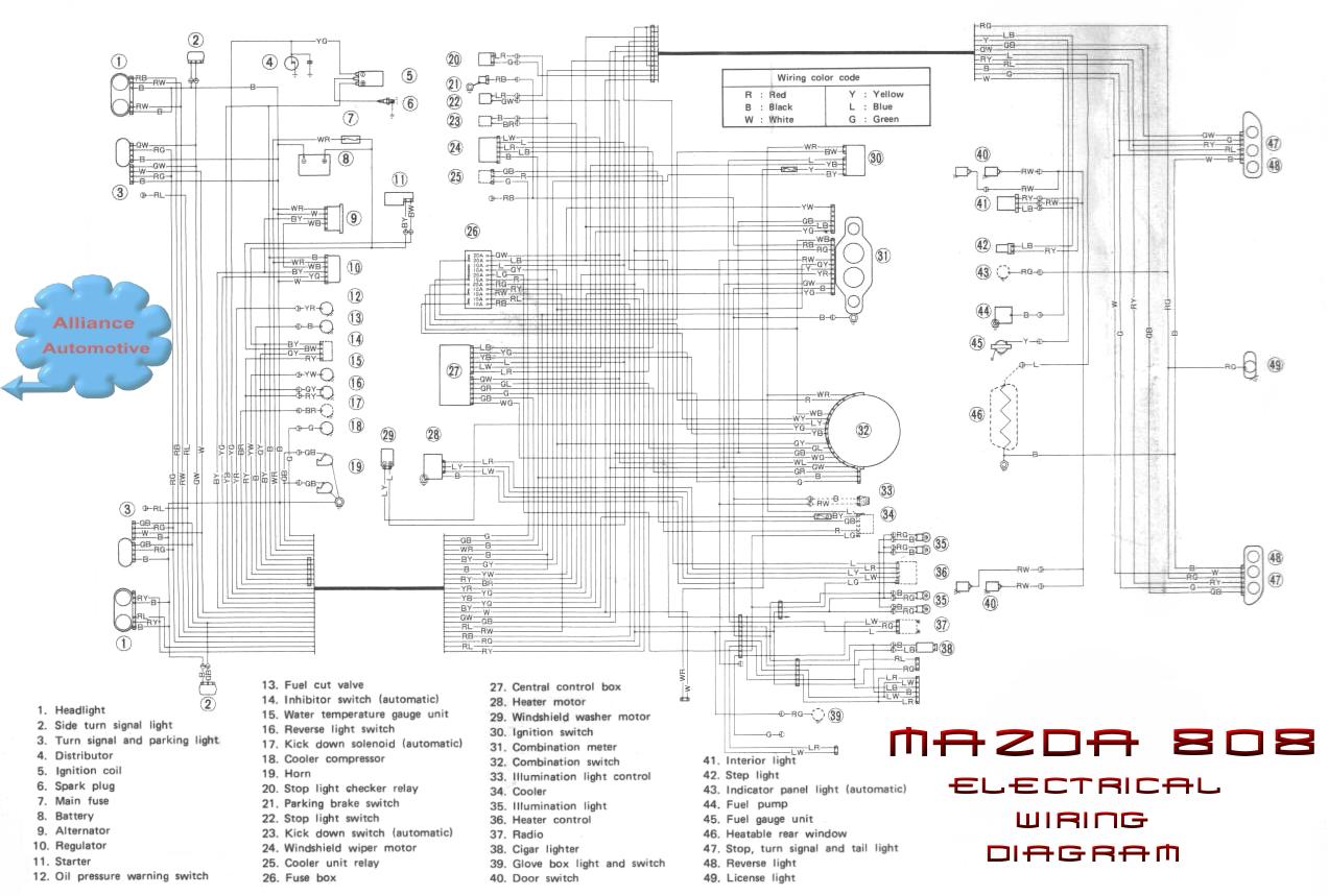
Temperature controller wiring diagram pdf. It reveals the elements of the circuit as streamlined forms and also the power and also signal links between the tools. Connect rtd1 rtd2 of a b rtd 6 7 8 910. Collection of pid temperature controller wiring diagram. Ause of mov across supply of temperature controller snubber circuits across loads are recommended buse s connection diagram. A 1211 revised wiring diagrams rev. The remainder of this section describes the temperature sensor wiring and the t775abm controller wiring.
Etc two stage electronic temperature control relay electrical ratings 120v 208240v no contact full load amps 98 a 49 a locked rotor amps 588 a 294 a resistive amps 98 a 49 a. A wiring diagram is a simplified standard photographic representation of an electric circuit. The ke2 evap offers quick pay. It reveals the components of the circuit as streamlined shapes and the power and also signal connections in between the devices. Pid vs on off 131 setting up as pid controller to set the controller as pid controller adjust the cntl control parameter. Controller wiring is terminated to the screw terminal blocks located inside the device.
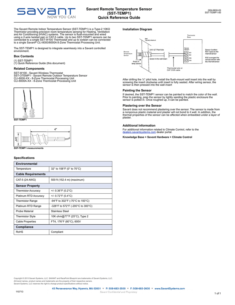
Sensor placed in well. Figure 7 illustrates the results of different regulation algorithms. The w1209 is an incredibly low cost yet highly functional thermostat controller. Short terminals 8 9. Bulletin 100 50 53 page 3 introduction the sporlan temperature control is a standalone controller used to regulate liquid or air temperature at a specific location by control ling a sporlan electric valve. A wiring diagram is a simplified traditional pictorial representation of an electrical circuit.
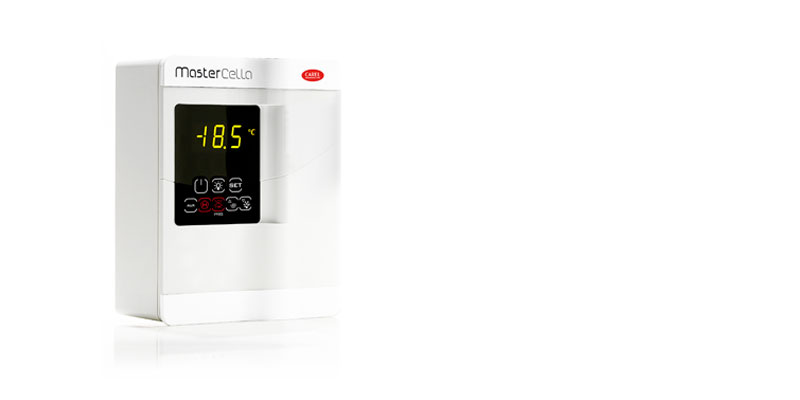
B 1215 revised relay output specifcation for sl4848 and sl4896. With this module you can intelligently control power to most types of electrical device based on the temperature sensed by the included high accuracy ntc temperature sensor. If accurate temperature control is not imperative then you may set the controller to on off. Although this module has an. Connect pt100 between terminal no. W1209 temperature control switch description.
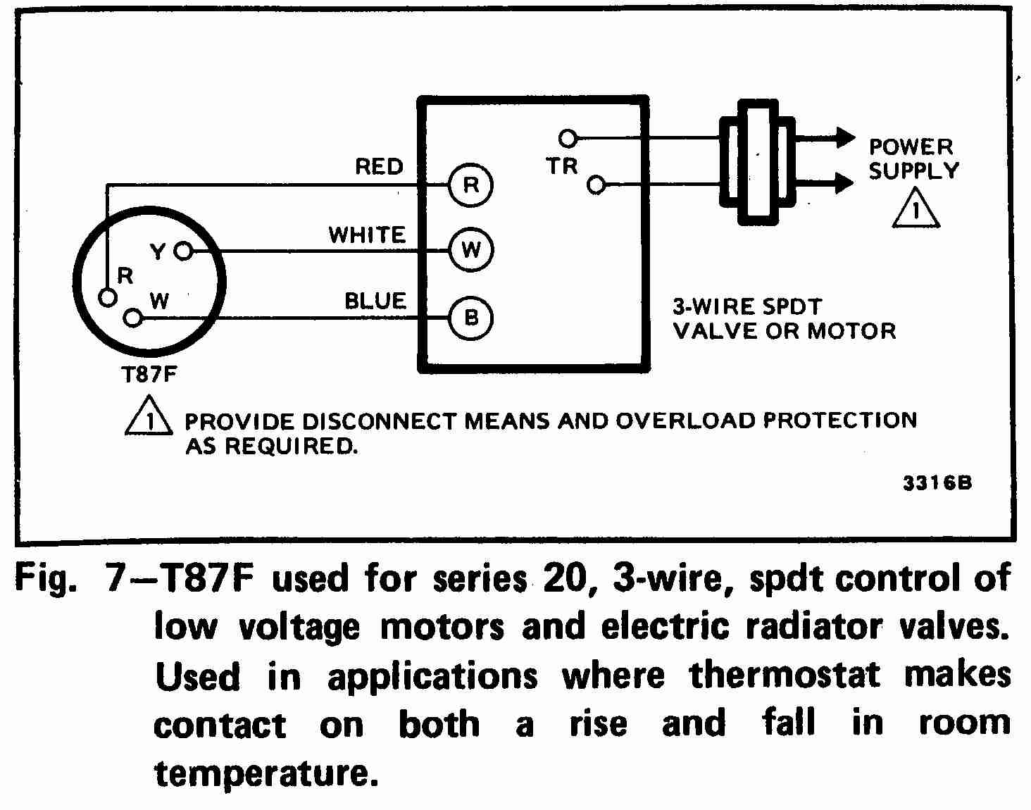
Solo temperature controller introduction 13. C 0418 revised chapter 6. All wiring must comply with applicable electrical codes and ordinances or as specified on installation wiring diagrams. Input and output wiring for typical wiring diagrams refer to figures 6 and 7. 7 8 2 for three wire pt 100. Collection of temperature controller wiring diagram.
Erated evaporator controller engineered to save energy in re frigeration systems through precise control of superheat space temperature fan cycling reducing compressor runtime and ke2 evaporator efficiency controls and communicates implementing demand defrosts.
Gallery of Temperature Controller Wiring Diagram Pdf