Collection of scion tc wiring diagram. Please refer to the manufacturers literature if in doubt.

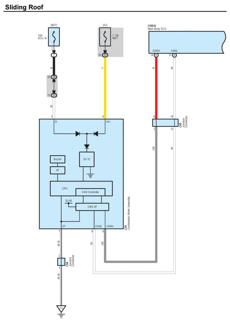
Scion Xb 2005 Overall Wiring Diagram Automotive
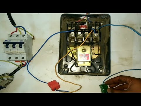
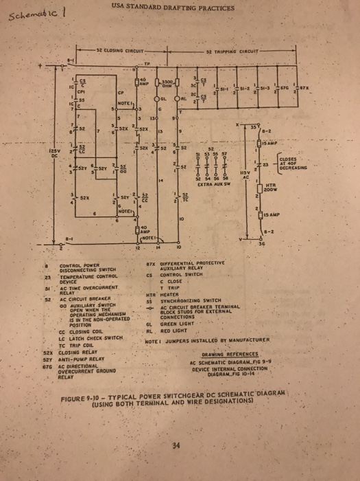
Tc motor starter wiring diagram. Refer to the motor manufacturers data on the motor for wiring diagrams on standard frame ex e ex d etc. A wiring diagram is a simplified standard pictorial depiction of an electric circuit. Wiring diagrams bulletin 609 manual starters are operated by start stop push buttons mounted on the front of the starter. Three phase motor connection schematic power and control wiring installation diagrams. It reveals the elements of the circuit as streamlined forms and the power as well as signal links between the devices. In this way the primary of the transformer is supplied with the same voltage as the powermotor circuit of the starter.
Figure 4 control power transformer wiring diagram. If you are not sure of how to make the connections on your equipment hire an electrician. Three phase motor connection stardelta without timer power control diagrams. Star delta y δ 3 phase motor starting method by automatic star delta starter with timer. Wiring diagrams do not show the operating mechanism since it is not electrically controlled. The security starter relay controlled car starter wiring diagram is as shown in the following picture.
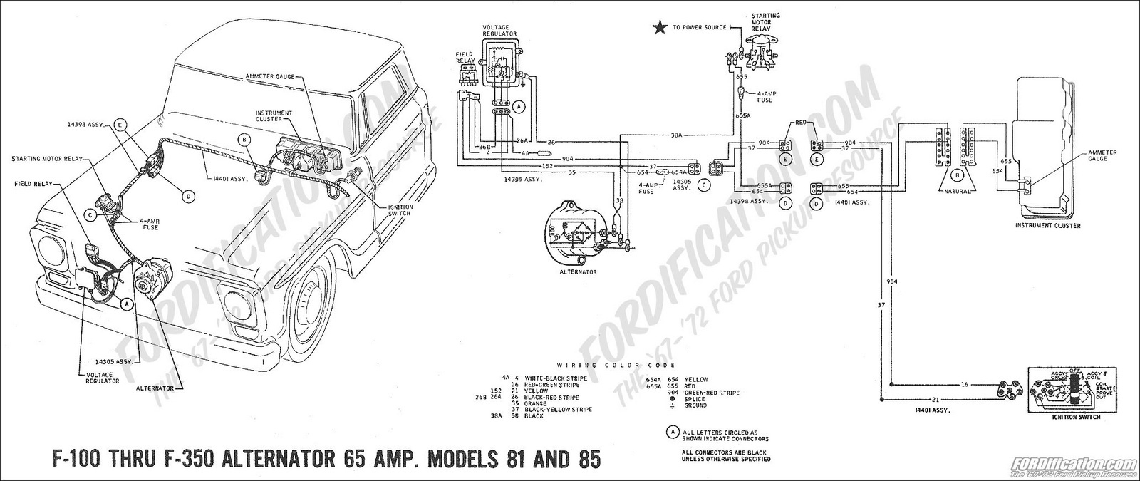
Before the engine starts the alternator does not generate electricity the voltage of the neutral tap n binding post is zero no current passes through the charge light relay starter relay coil and charging indicator relay contacts are connected to ground. The leads from the primary of the transformer are connected to l1 and l2 on the starter. These diagrams are current at the time of publication check the wiring diagram supplied with the motor. A motor starter is a combination of devices used to start run and stop an ac induction motor based on commands from an operator or a controller. Your motor starter may use wiring which is internal to the starter wiring which is different than the diagrams etc. In this video i demonstrate a 3 wire startstop circuit.
I describe each of the components involved such as the motor starter overload start pushbutton stop pushbutton and control power and. In north america an induction motor will typically operate at 230v or 460v 3 phase 60 hz and has a control voltage of 115 vac or 24 vdc. They are used in applications which do not require undervoltage protection. Inst maint wiringqxd 5032008 1002 am page 6.
Gallery of Tc Motor Starter Wiring Diagram